Magnetic fluid sealing device for gasholder

A magnetic fluid sealing and gas tank technology, applied in the field of gas tank, can solve the problems of difficult maintenance, complex structure, restraint, etc., and achieve the effects of simple structure, convenient maintenance and good stability

Active Publication Date: 2016-02-24
WISDRI ENG & RES INC LTD
View PDF7 Cites 5 Cited by
  • Summary
  • Abstract
  • Description
  • Claims
  • Application Information

AI Technical Summary

Problems solved by technology

Thin oil-sealed and dry-oil-sealed gas holders are complex in structure, difficult to maintain, and have a high one-time construction investment; although rubber-membrane-sealed gas holders have simple sealing methods, good sealing performance, and less maintenance workload, they are not suitable for large-scale development. For the trend of gas holders with good capacity, good stability, and easy maintenance, there is a bottleneck problem. For example, after the capacity of the gas cabinet is increased, the height of the rubber membrane will be increased, which requires a higher strength of the rubber membrane. However, this is limited by the current rubber Membrane Manufacturing Process
It can be seen that the gas holders of the above three traditional sealing methods have certain disadvantages in the development of large-scale gas cabinets, which hinder the process of large-scale gas cabinets

Method used


Image

  • Magnetic fluid sealing device for gasholder
  • Magnetic fluid sealing device for gasholder
  • Magnetic fluid sealing device for gasholder

Examples


Embodiment Construction

[0018] The technical solution of the present invention will be described in detail below in conjunction with the accompanying drawings and embodiments.

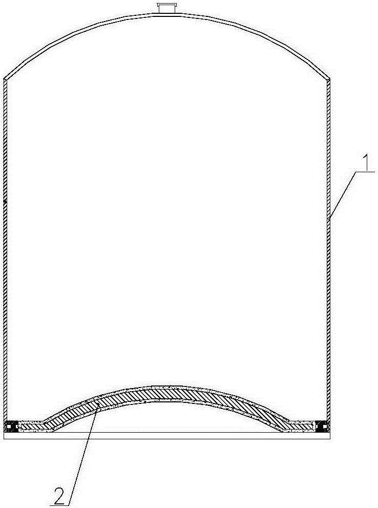
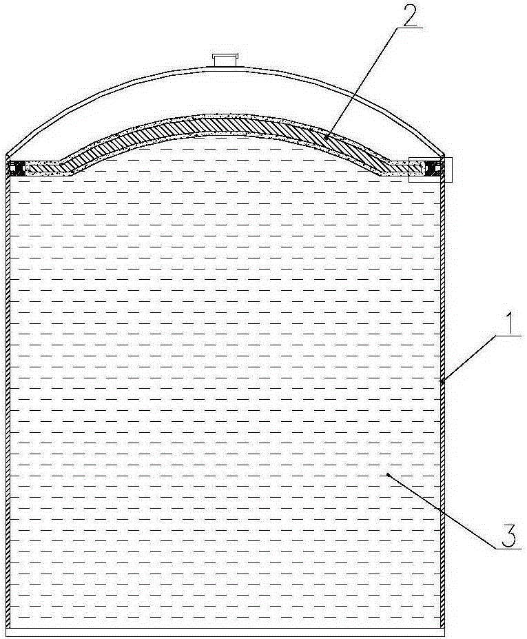
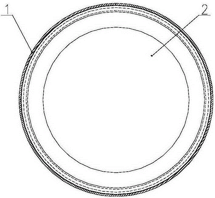
[0019] refer to Figure 1~Figure 3 As shown, the gas cabinet is mainly composed of two main parts of the cabinet body 1 and the piston 2, usually the cabinet body 1 is a cylindrical structure (such as figure 1 shown), the piston 2 is a disc-shaped structure (such as image 3 As shown), the piston 2 moves up and down in the cabinet 1 under the action of the gas 3 to realize the functions of storing the gas 3 and stabilizing the pressure of the gas 3 . When the piston 2 moves up and down in the cabinet body 1, a good seal between the piston 2 and the inner wall of the cabinet body 1 is required.

[0020] Such as Figure 4 As shown, the magnetic fluid sealing device of the gas cabinet according to the present invention is installed between the piston 2 and the inner wall of the cabinet body 1, including the upper pole shoe 4,...


PUM


Abstract

The invention discloses a magnetic fluid sealing device for a gasholder. The magnetic fluid sealing device is installed between a piston of the gasholder and the inner wall of a holder body, and comprises an upper pole shoe, a lower pole shoe, a permanent magnet, pole teeth and a magnetic fluid, wherein the upper pole shoe and the lower pole shoe are of an annular structure respectively, and located on the upper part and the lower part of a disc edge of the piston respectively, and the upper pole shoe and the lower pole shoe are both magnetic conductors; the permanent magnet is clamped between the upper pole shoe and the lower pole shoe, is of an annular structure, and is out of touch with the piston; the plurality of pole teeth are provided, and arranged on the end parts of the upper pole shoe and the lower pole shoe, a certain gap is kept between the end part of each pole tooth and the inner wall of the holder body, and the magnetic fluid is injected in each gap; the holder body is made of a metal magnetic conductor material, the piston is made of a non-metal non-magnetic conductive material, and the magnetic fluid is a magnetic liquid. The sealing device disclosed by the invention is bidirectional, applicable to gas holders with various capacities, simple in structure, high in stability, and convenient to maintain because only the magnetic fluid needs to be regularly supplemented; and with the adoption of the sealing device, the invalid capacity of the gas holder is small, and the construction cost is greatly reduced.

Description

technical field [0001] The invention relates to the technical field of gas cabinets, in particular to a magnetic fluid sealing device for a gas cabinet. Background technique [0002] As the low-carbon economy has gradually become the goal of economic and industrial development in various countries, and my country's environmental policy has also become more and more perfect, low-carbon production has become a very urgent issue in front of energy-consuming enterprises such as iron and steel metallurgy. Among them, as an important device for iron and steel enterprises to improve the comprehensive utilization rate of energy, the gas cabinet is more and more widely used. The function of the gas cabinet is to recover the instantaneous excess gas caused by the unbalanced production of throughput, and cooperate with the buffer user to achieve the ideal effect of pipe network voltage stabilization and energy saving. [0003] Gas holders are divided into two types: wet gas holders an...

Claims


Application Information

Patent Timeline
Patent Type & Authority Applications(China)
IPC IPC(8): F17B1/04
CPCF17B1/04
Inventor 严淑
Owner WISDRI ENG & RES INC LTD
Why Eureka
Try Eureka