
Resin trapper for nuclear power plant

A technology of resin traps and nuclear power plants, which is applied in nuclear engineering, chemical instruments and methods, fixed filter elements, etc., can solve the problems of large construction impact, short service life of the rubber lining layer, and shortened service life of the rubber lining, etc., to achieve The effect of low installation and operation requirements, low ambient temperature requirements, and extended service life

Inactive Publication Date: 2016-02-24
中广核工程有限公司 +1
View PDF5 Cites 1 Cited by
  • Summary
  • Abstract
  • Description
  • Claims
  • Application Information

AI Technical Summary

Problems solved by technology

Dismantling equipment and relining rubber will incur high costs, such as the condensate water treatment system in the main building of the nuclear power plant. When dismantling equipment, it is necessary to dismantle a large number of pipeline valves related to the equipment and the partition wall that affects the removal of the equipment. The construction has a large impact and a long period
If the re-lining of equipment and the restoration of the system cannot be completed within an overhaul period of the nuclear power plant, it will seriously affect the normal operation of the nuclear power unit
[0006] 2) The transportation, storage, and use of the rubber liner have strict environmental requirements. When the ambient temperature is lower than 5°C, direct sunlight and excessive temperature may damage the rubber liner layer. Long-term storage of empty tanks outdoors before equipment installation will accelerate The rubber is aging, and the operating temperature is too high, which will shorten the life of the rubber lining of the equipment
In addition, the rubber lining layer is easily damaged. After the rubber lining is completed, any welding on the rubber lining equipment will damage the rubber lining layer, and the slight bumping of the rubber lining during transportation and installation will also damage the rubber lining, causing the equipment to return to the factory for re-lining
[0007] 3) If the quality control of the rubber lining of new equipment is not strict or the transportation, storage and installation are not carried out according to the specifications, the service life of the rubber lining layer will be shorter, and there may be trace amounts of dissolved substances during the operation of the system, which will affect the water quality of the equipment effluent
If there is a small damage or defect in the rubber lining layer, it is very difficult to repair, and the service life of the rubber lining after repair is greatly shortened
[0009] 5) The manhole flange and flange cover on the top of the resin trap have a large fastening torque, and if the tightening operation is slightly careless, the rubber-lined sealing surface will be damaged. During the equipment installation and commissioning stages, the manhole cover needs to be disassembled and assembled repeatedly. It will also damage the rubber lining of the sealing surface. After the rubber lining of the sealing surface is damaged, it cannot be repaired on site. It can only be returned to the factory to re-line the rubber.
However, medium-voltage equipment needs a thicker equipment wall thickness to meet the structural strength requirements, and the material consumption is large, resulting in high cost of all stainless steel equipment, which is difficult to popularize and apply

Method used


Image

  • Resin trapper for nuclear power plant
  • Resin trapper for nuclear power plant

Examples


no. 1 approach

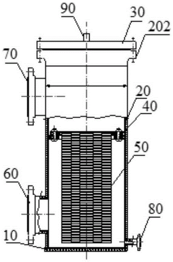
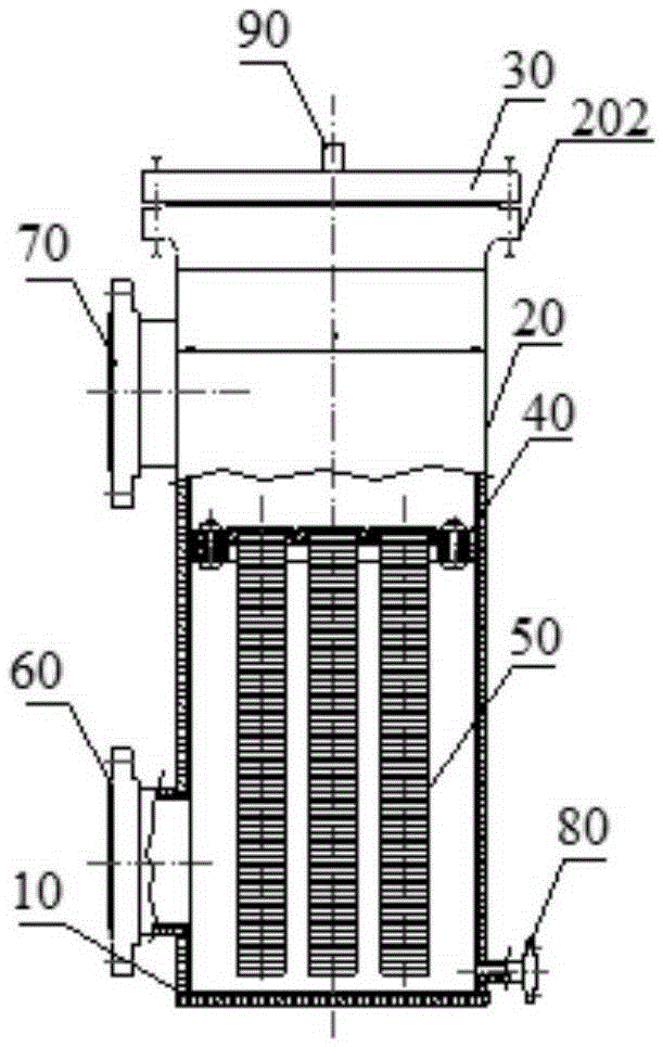
[0030] see figure 1 As shown, the resin catcher for nuclear power plants of the present invention is a first embodiment of a high-flow medium-pressure resin catcher comprising: a bottom plate 10, a cylinder 20 installed on the bottom plate 10, and a manhole flange 202 assembled on the cylinder 20 The manhole cover plate 30 on the top, the filter element installation perforated plate 40 arranged in the cylinder body 20 and the filter element 50 positioned in the cylinder body 20 through the filter element installation perforated plate 40, and the water inlet 60 arranged on the side wall of the cylinder body 20 And water outlet 70.

[0031] exist figure 1 In the illustrated embodiment, the bottom plate 10, the cylinder body 20, the manhole cover plate 30, the water inlet 60 and the water outlet 70 are made of bimetal composite steel plates. The inner wall of the composite steel plate is made of thinner stainless steel plate that meets the anti-corrosion requirements, the outer...


PUM


Abstract

The invention discloses a resin trapper for a nuclear power plant. The resin trapper comprises a bottom plate, a cylinder arranged on the bottom plate, a manhole cover plate assembled on the cylinder, a filter element mounting porous plate arranged in the cylinder, a filter element positioned in the cylinder by virtue of the filter element mounting porous plate, and a water inlet and a water outlet which are formed in the side wall of the cylinder, wherein the bottom plate, the cylinder, the manhole cover plate, the water inlet and the water outlet are manufactured by bimetallic composite steel plates; the inner layer refers to stainless steel plates; the outer layer refers to vessel steel plates; and the filter element mounting porous plate and the filter element are made of all stainless steel. According to the resin trapper for the nuclear power plant disclosed by the invention, the bimetallic composite steel plates are adopted, a layer of thin stainless steel plates is compounded on the inner side of an equipment container, the original rubber lined layer is replaced, and the defect that the rubber lined layer is short in service life is overcome. Compared with an all stainless steel material, the material in the invention has the advantages that the construction cost is greatly reduced, and the anticorrosion requirement is met. In the nuclear power plant operating process, the resin trapper for the nuclear power plant disclosed by the invention does not need to be maintained and replaced in the unit lifecycle under the normal use condition.

Description

technical field [0001] The invention belongs to the field of industrial water treatment, and more specifically, the invention relates to a resin catcher for nuclear power plants. Background technique [0002] In high-purity water purification treatment systems (such as nuclear power plant industrial water treatment systems), ion exchange is generally used to remove trace impurities in water. In order to prevent broken resin or resin leaking into the subsequent system due to problems with the internal components of the ion exchange device, it is necessary to install a resin trap behind the medium pressure, high flow rate ion exchanger. [0003] In order to avoid contamination of high-purity water by corrosion products produced by the corrosion of the resin trap body, the inner surface of the resin trap is generally anti-corrosion with carbon steel lining rubber. Rubber-lined anti-corrosion means that after the rubber plate is attached to the part of the equipment that is in ...

Claims


Application Information

Patent Timeline
Patent Type & Authority Applications(China)
IPC IPC(8): G21F9/12B01D29/05
CPCG21F9/12B01D29/05
Inventor 梁桥洪王志明杨光文詹媛
Owner 中广核工程有限公司
Learn More