
Fiber-optic gas laser generator for generating 1.5μm laser

A gas laser and generating device technology, applied in the field of lasers, can solve the problems of long effective distance, high pumping threshold, and low conversion efficiency, and achieve the effects of high damage threshold, reduced pumping threshold, and high peak power

Active Publication Date: 2016-08-24
NAT UNIV OF DEFENSE TECH
View PDF1 Cites 0 Cited by
  • Summary
  • Abstract
  • Description
  • Claims
  • Application Information

AI Technical Summary

Problems solved by technology

[0005] The object of the present invention is to provide a fiber-optic gas laser generating device for generating 1.5 μm laser. Technical problems of high threshold and low conversion efficiency

Method used


Image

  • Fiber-optic gas laser generator for generating 1.5μm laser

Examples


Embodiment Construction

[0024] The accompanying drawings constituting a part of this application are used to provide further understanding of the present invention, and the schematic embodiments and descriptions of the present invention are used to explain the present invention, and do not constitute an improper limitation of the present invention.

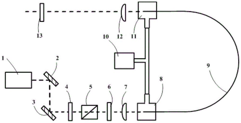
[0025] see figure 1 , the fiber gas laser generating device for generating 1.5 μm laser provided by the present invention includes: a pump source 1, a pump coupling device for coupling the pump laser light to a hollow-core photonic crystal fiber 9, a hollow-core photonic crystal fiber 9 and a quasi- Straight filtering device; the hollow photonic crystal fiber 9 is filled with working gas; the output end of the pump source 1 is optically connected to the input end of the pump coupling device, and the output end of the pump coupling device is optically connected to one end of the hollow photonic crystal fiber 9; The other end of the hollow-core photonic cr...


PUM


Abstract

The invention provides an optical fiber gas laser generation device used for generating 1.5-micron laser. Pumped laser is in stimulated Raman scattering interaction with a working gas filling a hollow photonic crystal optical fiber, so that laser of a 1.5-micron band can be outputted.

Description

technical field [0001] The invention relates to the technical field of lasers, in particular to an optical fiber gas laser generating device for generating 1.5 μm laser. Background technique [0002] The 1.5μm band laser has important application value in the fields of optical fiber communication, biomedicine, environmental monitoring and industrial processing, and has always been a hot spot of international research. Tunable, narrow linewidth, and high peak power 1.5μm band lasers can be used as ideal light sources for supercontinuum lasers, infrared gas lasers, or optical parametric oscillations. At present, the 1.5 μm light source is mainly obtained by rare earth ion-doped solid glass fiber lasers, but due to the low damage threshold of solid doped fibers and strong nonlinear effects, it is difficult to further increase the output laser power. Although the 1.5μm band laser with high peak power can be output by mode locking, Q switching and other methods, the nonlinear ef...

Claims


Application Information

Patent Timeline
Patent Type & Authority Patents(China)
IPC IPC(8): H01S3/067
CPCH01S3/06704H01S3/06712
Inventor 王泽锋陈育斌顾博陈子伦许晓军司磊陆启生
Owner NAT UNIV OF DEFENSE TECH
Learn More