Multi-resonance-layer hollow-core optical fiber

A hollow-core fiber, multi-resonance technology, applied in cladding fiber, glass fiber, optics, etc., can solve the problems of increasing fiber cladding nodes, large difference in wall thickness, affecting fiber characteristics, etc., to improve the damage threshold, limit The effect of reducing the loss and increasing the binding capacity

Active Publication Date: 2019-12-17
JIANGXI NORMAL UNIV
View PDF9 Cites 13 Cited by
  • Summary
  • Abstract
  • Description
  • Claims
  • Application Information

AI Technical Summary

Problems solved by technology

Later, it was found that nesting multi-dielectric tubes inside the dielectric tubes of the reflective layer can reduce the confinement loss to be lower than the surface scattering loss, but it is difficult to precisely control the size and position of each dielectric tube under the existing manufacturing process. The wall thickness of the two dielectric tubes in the optical fiber cladding is quite different, and the position and size of the small dielectric ring are different, which affects the characteristics of the optical fiber (from: [W.Belardi, "Design and properties of hollow antiresonant fibers for the visible and near infrared spectral range," J. Lightw. Technol., 32, 4497~4503, (2015)】)
Chinese patent application No. 201710954172.6 discloses a hollow-core anti-resonant optical fiber with multiple resonant layers. Adding a thin-walled layer to the capillary of the fiber cladding or using a capillary as a supporting component to increase the fiber cladding can reduce the fiber loss, but the above method The nodes in the fiber cladding are increased, thus causing too many cladding modes, and precise adjustments are required in the fiber manufacturing process to avoid the influence of the cladding modes at the nodes

Method used


Image

  • Multi-resonance-layer hollow-core optical fiber
  • Multi-resonance-layer hollow-core optical fiber
  • Multi-resonance-layer hollow-core optical fiber

Examples


Embodiment Construction

[0020] The following will clearly and completely describe the technical solutions in the embodiments of the present invention with reference to the accompanying drawings in the embodiments of the present invention. Obviously, the described embodiments are only some of the embodiments of the present invention, not all of them. Based on the embodiments of the present invention, all other embodiments obtained by persons of ordinary skill in the art without making creative efforts belong to the protection scope of the present invention.

[0021] see Figure 1-4 , the present invention provides a technical solution:

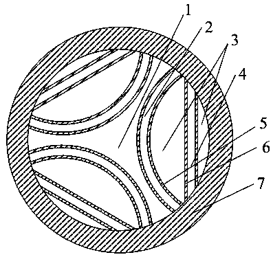
[0022] The multi-resonant layer hollow-core optical fiber of this embodiment includes a ring-shaped dielectric tube 7, and the inner center of the ring-shaped dielectric tube 7 is provided with a first-type hole 1, the first-type hole 1 is an optical fiber core, and the first-type Several groups of arc-shaped dielectric layers 5 are arranged around the hole 1, and a ...


PUM


Abstract

The invention discloses a multi-resonance-layer hollow-core optical fiber, which comprises an annular dielectric pipe, wherein a first type hole is formed in the central position in the annular dielectric pipe; a plurality of groups of arc-shaped dielectric layers are arranged around the first type hole, a rectangular dielectric layer is arranged on the inner side of each arc-shaped dielectric layer; a second type hole is formed between every two groups of arc-shaped dielectric layers in the same arc direction; third type holes are formed between each rectangular dielectric layer and the innerwall of the annular dielectric pipe and between each rectangular dielectric layer and the corresponding arc-shaped dielectric layer, a fourth type hole is formed between every two groups of adjacentrectangular dielectric layers, the first type hole, the second type holes, the third type holes and the fourth type holes form a low-refractive-index region, and the arc-shaped dielectric layers, therectangular dielectric layers and the annular dielectric pipe form a high-refractive-index region. The multi-resonance-layer hollow-core optical fiber has the beneficial effects that the damage threshold of the optical fiber is improved; the confinement loss of the optical fiber is reduced, and the low confinement loss features can be obtained conveniently; and high-bandwidth and low-loss opticaltransmission can be obtained in a facilitated manner.

Description

technical field [0001] The invention relates to the field of optical fiber communication, in particular to a multi-resonance layer hollow-core optical fiber. Background technique [0002] The anti-resonant hollow-core fiber has less strict requirements on the periodicity of the air holes in the cladding, and can obtain ultra-wide transmission bandwidth by controlling the resonant coupling wavelength. Therefore, the anti-resonant hollow-core fiber has low and high manufacturing process requirements. In order to obtain high-quality optical fiber transmission characteristics, it is necessary to overcome the adverse effects of nodes at the junction of each unit in the fiber cladding and avoid loss in the anti-resonance window. The appearance of the peak improves the loss and dispersion characteristics of the fiber. At the same time, in order to reduce the transmission loss of optical fibers, researchers have proposed anti-resonant hollow-core optical fibers with various structu...

Claims


Application Information

Patent Timeline
Patent Type & Authority Applications(China)
IPC IPC(8): G02B6/02
CPCG02B6/02304G02B6/02328G02B6/02395C03B37/02781C03B2203/14C03B2203/16C03B2203/42
Inventor 祝远锋罗海梅柯强徐裕富
Owner JIANGXI NORMAL UNIV
Why Eureka
Try Eureka