

MMC submodule topological structure based on H-bridge
A topology and sub-module technology, applied in the field of flexible power transmission and distribution, can solve the problems of low utilization rate of the switch state and limit the engineering application of MMC sub-modules, and achieve the effect of reducing capacitance, reducing module volume and improving power density
- Summary
- Abstract
- Description
- Claims
- Application Information
AI Technical Summary
Problems solved by technology
Method used
Image

Examples
Embodiment Construction
[0020] The present invention will be further explained below in conjunction with specific embodiments and accompanying drawings.
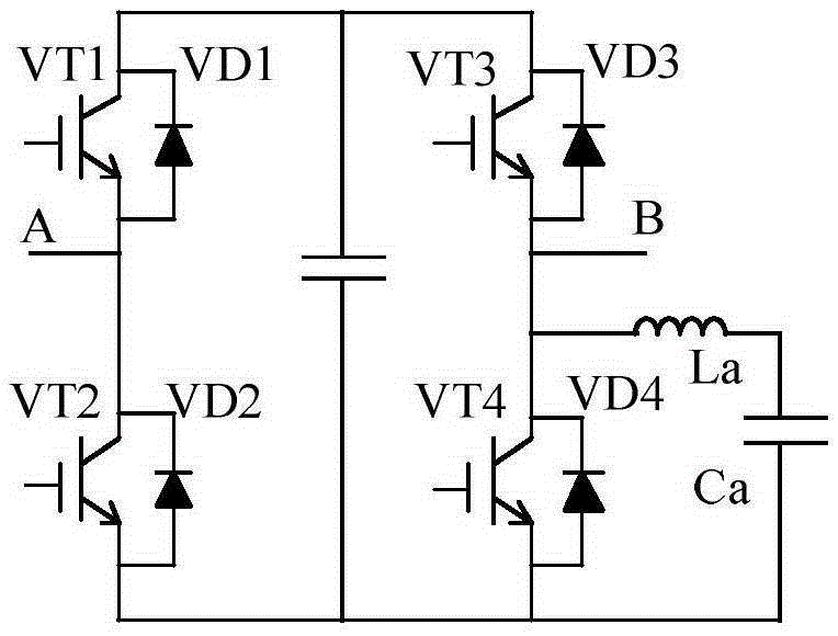
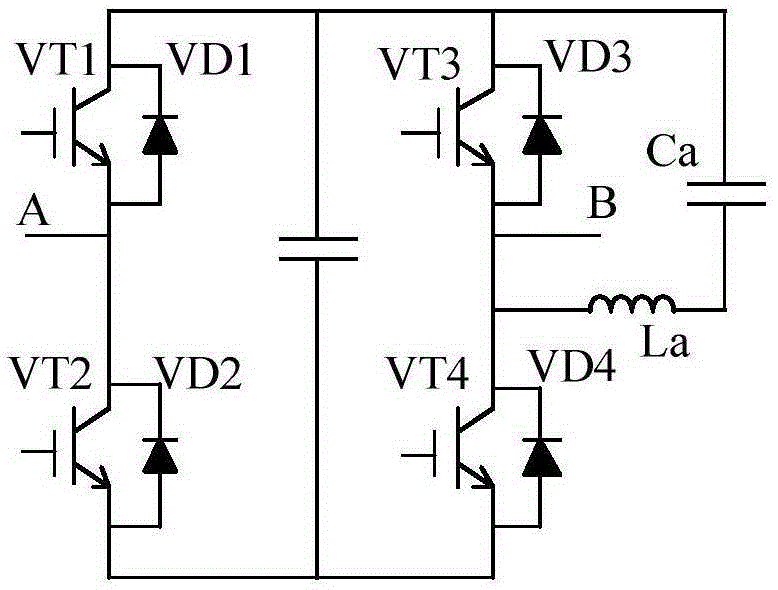
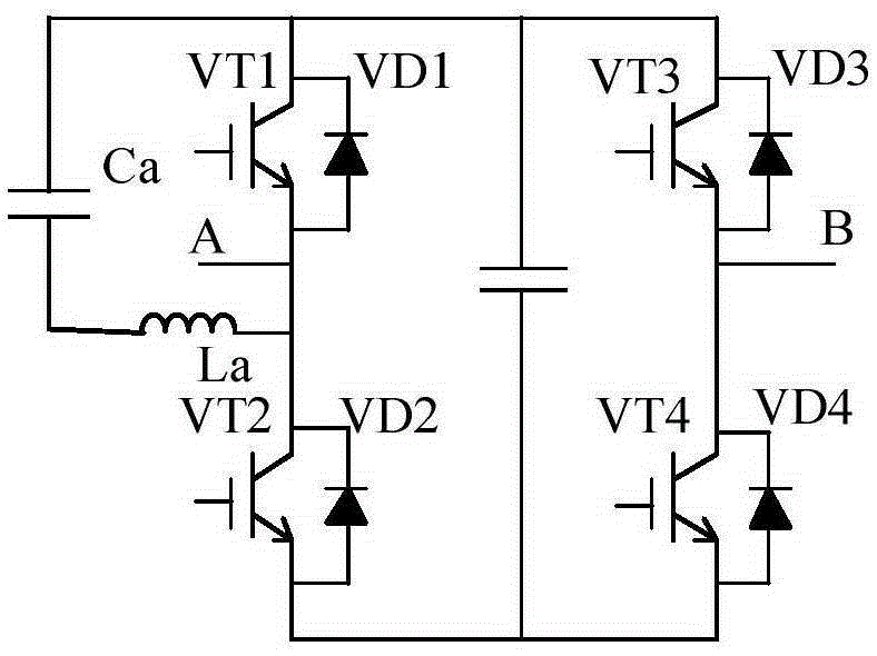
[0021] see Figure 1a ~ Figure 1d , the present invention includes four IGBT tubes connected in sequence, the four IGBT tubes include the first IGBT tube VT1, the second IGBT tube VT2, the third IGBT tube VT3 and the fourth IGBT tube VT4, the emitter stage of the first IGBT tube VT1 is connected to the The collector of the second IGBT tube VT2 is connected, the emitter of the third IGBT tube VT3 is connected to the collector of the fourth IGBT tube VT4, between the collector of the first IGBT tube VT1 and the collector of the third IGBT tube VT3, the second The emitter of the second IGBT tube VT2 and the emitter of the fourth IGBT tube VT4 are connected through the H bridge bus, the first IGBT tube VT1 and the second IGBT tube VT2 form the first half-bridge structure, the third IGBT tube VT3 and the second IGBT tube VT3 Four IGBT tubes VT4 consti...
PUM
 Abstract
Description
Claims
Application Information