
Combined water tank type boiler waste heat recovery device

A boiler waste heat recovery device technology, applied to steam boilers, steam boiler accessories, steam boiler components, etc., can solve the problems of low recovery efficiency and large energy waste, achieve efficient recovery and utilization, improve heat storage efficiency, heat Effects of improved recycling efficiency

Inactive Publication Date: 2016-03-02
秦开俭
View PDF0 Cites 0 Cited by
  • Summary
  • Abstract
  • Description
  • Claims
  • Application Information

AI Technical Summary

Problems solved by technology

[0002] The traditional boiler waste heat recovery device generally uses a hot water tank outside the chimney to absorb the heat of the chimney by thermal melting of water. Although this method can also recover heat, its recovery efficiency is low and energy waste is large

Method used


Image

  • Combined water tank type boiler waste heat recovery device

Examples


Embodiment Construction

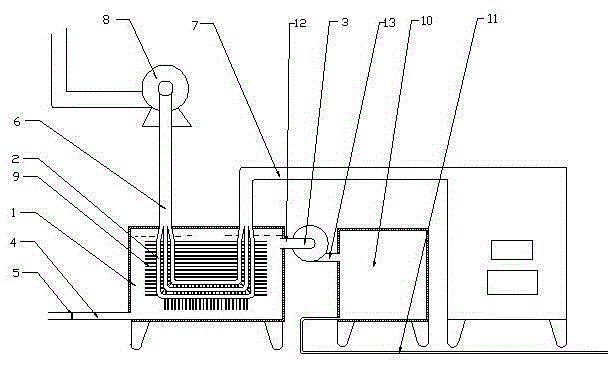
[0012] exist figure 1 Among them, a heat absorbing tank 1 is set, and a heat absorbing tank inlet pipe 4 and a heat absorbing tank outlet pipe 12 are arranged on the heat absorbing tank 1. A plurality of metal cooling fins 9 are arranged on the flue 6, the smoke inlet of the u-shaped flue 6 is connected with the boiler chimney 7, the smoke outlet of the u-shaped flue 6 is connected with the induced draft fan 8, and a reserve hot water tank 10 is arranged, An insulation layer is set outside the reserve hot water tank 10, a reserve heat water tank inlet pipe 13 and a reserve heat water tank outlet pipe 11 are arranged on the reserve heat water tank 10, and an insulation layer is set around the heat absorbing tank 1, and the heat absorbing tank A temperature-controlled valve 5 is set on the water-absorbing tank inlet pipe 4 of 1, and a temperature-controlled water pump 3 is set between the water-absorbing tank outlet pipe 12 of the heat-absorbing tank 1 and the reserve hot water ...


PUM


Abstract

Disclosed is a combined water tank type boiler waste heat recovery device. A heat absorption water tank is arranged on the combined water tank type boiler waste heat recovery device. A heat absorption water tank water inflow tube and a heat absorption water tank water outflow tube are arranged on the heat absorption water tank. The combined water tank type boiler waste heat recovery device is characterized in that a u-shaped flue is arranged in the heat absorption water tank, multiple metal cooling sheets are arranged on the u-shaped flue, a smoke inlet of the u-shaped flue is connected with a boiler chimney, and a smoke outlet of the u-shaped flue is connected with a draught fan; a hot water reserve tank is further arranged on the combined water tank type boiler waste heat recovery device; a thermal-insulation layer is arranged outside the hot water reserve tank, a hot water reserve tank water inflow tube and a hot water reserve tank water outflow tube are arranged on the hot water reserve tank, and a thermal-insulation layer is arranged around the heat absorption water tank; a temperature control valve is arranged on the heat absorption water tank water inflow tube of the heat absorption water tank, and a temperature control water pump is further arranged between the heat absorption water tank water outflow tube of the heat absorption water tank and the hot water reserve tank.

Description

technical field [0001] The invention relates to a boiler waste heat recovery device, in particular to a composite water tank type boiler waste heat recovery device. Background technique [0002] Traditional boiler waste heat recovery devices generally use a hot water tank outside the chimney to absorb the heat of the chimney by the thermal fusion of water. Although this method can also recover heat, its recovery efficiency is low and energy waste is large. Contents of the invention [0003] The object of the present invention is to provide a waste heat recovery device for composite water tank boilers with simple structure and high efficiency. [0004] The present invention utilizes a heat-absorbing tank and a reserve heat-water tank. When the water in the heat-absorbing tank reaches the set temperature, the temperature-controlled water pump is started to inject hot water into the reserve heat-water tank for storage, and the two water tanks are installed outside Insulation...

Claims


Application Information

Patent Timeline
Patent Type & Authority Applications(China)
IPC IPC(8): F24H9/00F22B37/00
CPCF24H9/0005F22B37/00
Inventor 秦开俭
Owner 秦开俭
Learn More