Dual-crank arm type piezoelectric-electromagnetic composite power generation device

An electromagnetic composite and power generation device technology, which is applied to electromechanical devices, piezoelectric effect/electrostrictive or magnetostrictive motors, generators/motors, etc., can solve problems such as small power generation, poor adaptability, and poor low-frequency adaptability , to achieve the effect of increasing the power

Inactive Publication Date: 2016-03-02
CHINA UNIV OF GEOSCIENCES (WUHAN)
View PDF6 Cites 25 Cited by
  • Summary
  • Abstract
  • Description
  • Claims
  • Application Information

AI Technical Summary

Problems solved by technology

[0004] In view of the problems of poor environmental adaptability, low power generation efficiency, poor low-frequency adaptability, and small power generation per unit time of existing piezoelectric vibration power generation devices, in order to make piezoelectric power generation devices more adaptable to random, broadband, low-frequency, large-amplitude and High-intensity vibration energy recovery, the present invention provides a hyperbolic-arm type piezoelectric-electromagnetic composite power generation device, through the use of a new type of overall structure of the hyperbolic-arm type piezoelectric-electromagnetic composite power generation vibrator, and the synergistic effect generated, to optimize the power generation The purpose of the overall performance of the device

Method used


Image

  • Dual-crank arm type piezoelectric-electromagnetic composite power generation device
  • Dual-crank arm type piezoelectric-electromagnetic composite power generation device
  • Dual-crank arm type piezoelectric-electromagnetic composite power generation device

Examples


Embodiment Construction

[0028] In order to have a clearer understanding of the technical features, purposes and effects of the present invention, the specific implementation manners of the present invention will now be described in detail with reference to the accompanying drawings.

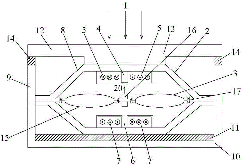
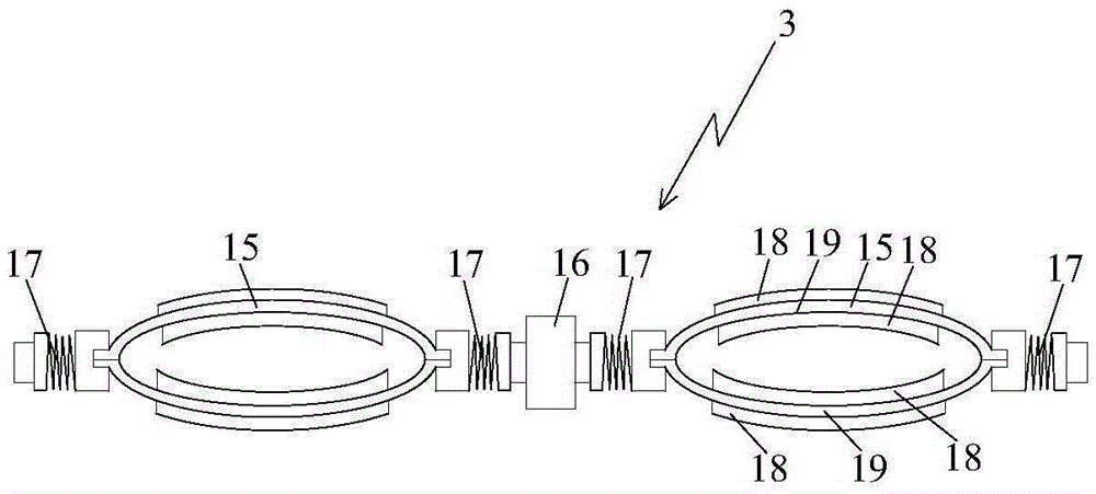
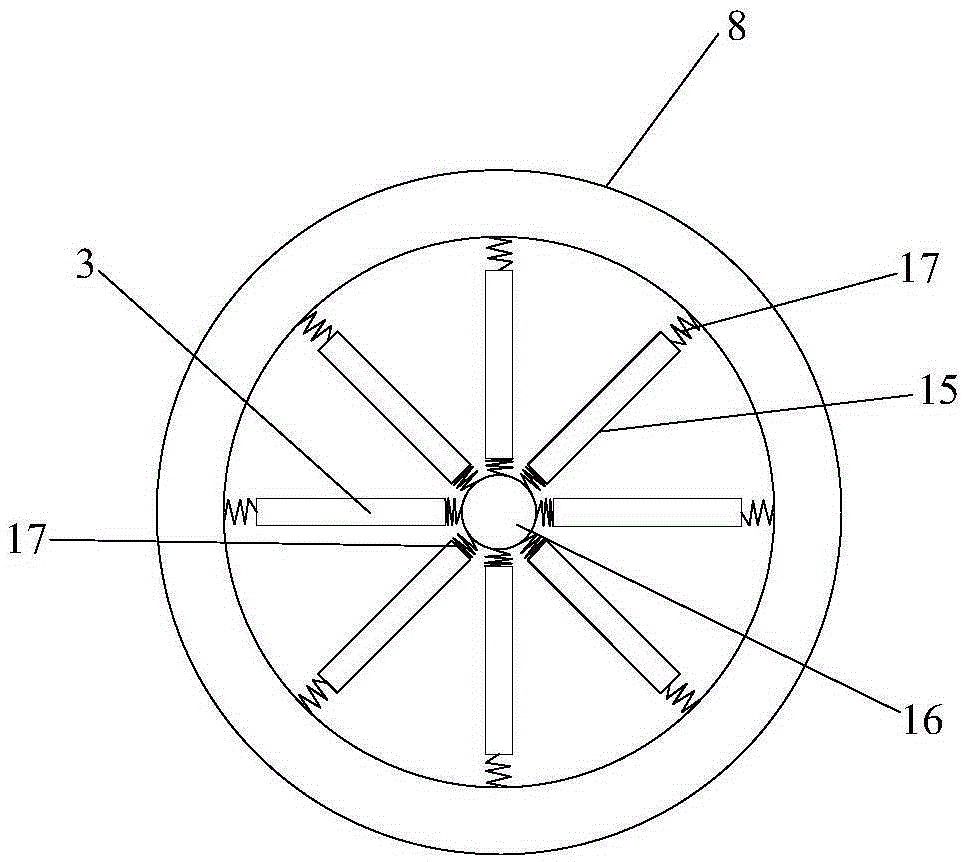
[0029] The structural longitudinal section schematic diagram of the hyperbolic arm type piezoelectric-electromagnetic composite power generation device of the present invention is as follows: figure 1 As shown, it includes: a hyperbolic piezoelectric-electromagnetic composite transducer 2 . The hyperbolic piezoelectric-electromagnetic composite transducer 2 includes: the hyperbolic piezoelectric-electromagnetic composite generator vibrator 3, the upper permanent magnet 4, the upper induction coil 5, the lower permanent magnet 6, the lower induction coil 7 and the piezoelectric - Electromagnetic composite transducer box 8 . The piezoelectric-electromagnetic composite transducer box 8 adopts a cymbal-shaped structural bo...


PUM


Abstract

The invention relates to a dual-crank arm type piezoelectric-electromagnetic composite power generation device. The composite power generation device comprises a dual-crank arm type piezoelectric-electromagnetic composite transducer; the dual-crank arm type piezoelectric-electromagnetic composite transducer comprises a dual-crank arm type piezoelectric-electromagnetic composite power generation oscillator, an upper permanent magnet layer, an upper induction coil layer, a lower permanent magnet layer, a lower induction coil layer and a piezoelectric-electromagnetic composite transducer box; the upper permanent magnet layer is arranged in the middle of the upper induction coil layer; the lower permanent magnet layer is arranged in the middle of the lower induction coil layer; and the dual-crank arm type piezoelectric-electromagnetic composite power generation oscillator is arranged between the upper and lower permanent magnets, and the induction coils. A dual-crank arm type piezoelectric oscillator, a permanent magnet mass block and a rigidity-variable spring of the dual-crank arm type piezoelectric-electromagnetic composite power generation oscillator form an overall structure to generate a certain synergistic effect, so that the composite power generation device is relatively low in resonant frequency and relatively high in amplitude, and generated electric quantity is obviously increased; and therefore, the composite power generation device is widely applicable to the recycling fields of random, wideband, low-frequency, high-amplitude, and high-strength vibration energy in the environments.

Description

technical field [0001] The invention relates to the technical field of new energy, and more specifically, relates to a hyperbolic-arm type piezoelectric-electromagnetic composite power generation device. Background technique [0002] At present, in terms of using piezoelectric materials to recycle environmental energy for power generation, most of them are for the purpose of recycling vibration energy. As we all know, for the vibrating piezoelectric power generation device, it is often because when the natural frequency of the piezoelectric vibrator is equal to the vibration frequency of the environment, a higher power generation capacity and energy conversion efficiency can be achieved. However, due to the existence of the piezoelectric vibrator itself, the resonant frequency is usually high, among which the resonant frequency of the piezoelectric cantilever can reach hundreds of Hz, and the resonant frequency of the circular piezoelectric vibrator is also as high as severa...

Claims


Application Information

Patent Timeline
Patent Type & Authority Applications(China)
IPC IPC(8): H02N2/18H02K35/02
CPCH02K35/02H02N2/186
Inventor 袁曦明袁一楠
Owner CHINA UNIV OF GEOSCIENCES (WUHAN)
Why Eureka
Try Eureka