
Fuel pump

A fuel pump and fuel technology, which is applied in the direction of fuel injection pump, pump, fuel injection device, etc., can solve the problems of high noise of fuel pump and loud collision sound.

Active Publication Date: 2016-03-02
AISAN IND CO LTD
View PDF7 Cites 0 Cited by
  • Summary
  • Abstract
  • Description
  • Claims
  • Application Information

AI Technical Summary

Problems solved by technology

If the relative speed of the shaft with respect to the end of the cover is high, the impact sound becomes louder, so the noise generated by the fuel pump becomes louder as the vibration of the fuel pump increases

Method used


Image

  • Fuel pump
  • Fuel pump
  • Fuel pump

Examples


Embodiment Construction

[0016] Embodiments of the present invention will be described below with reference to the drawings.

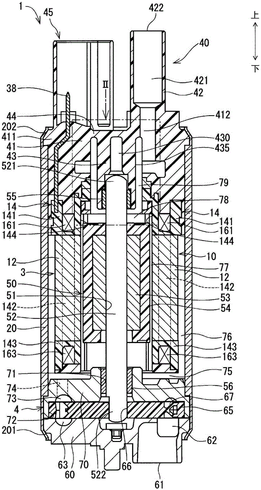
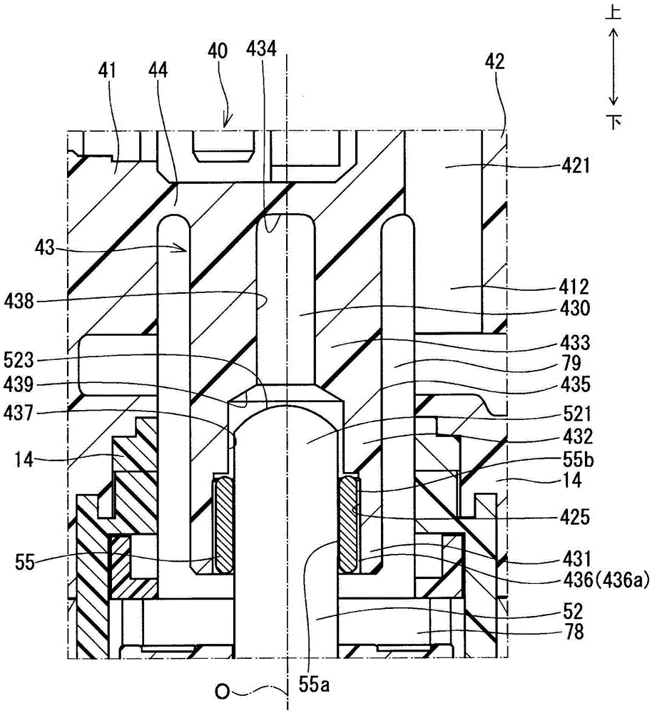
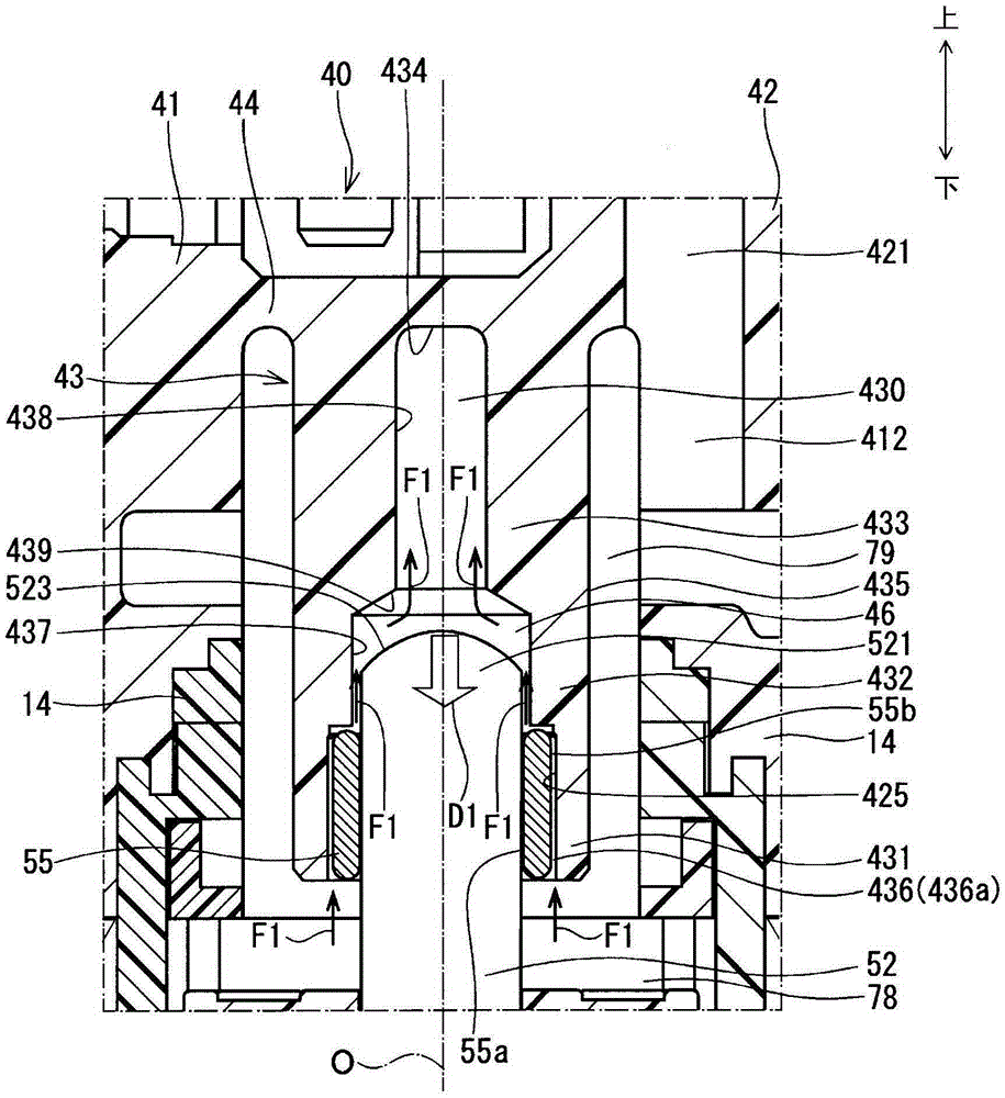
[0017] according to Figure 1 ~ Figure 4 A fuel pump according to one embodiment of the present invention will be described.

[0018] The fuel pump 1 includes a motor unit 3 , a pump unit 4 , a casing 20 , a pump cover 60 , a cover end 40 , and a bearing housing 43 . In the fuel pump 1 , the motor unit 3 and the pump unit 4 are accommodated in a space formed by the housing 20 , the pump cover 60 and the cover end 40 . fuel pump 1 from figure 1 The suction port 61 shown on the lower side sucks the fuel in the fuel tank not shown, and figure 1 The discharge port 422 shown on the upper side of , discharges to the internal combustion engine. In addition, in Figure 1~4 , let the upper side be "upper side" and the lower side be "lower side".

[0019] The casing 20 is formed in a cylindrical shape from metal such as iron.

[0020] The pump cover 60 closes the end 201 of the c...


PUM


Abstract

In a cover end (40) provided on the end of a housing, a bearing receiving unit (43) is provided on the inner side of the housing. The bearing receiving unit (43) has a receiving space (430) which receives a bearing (55) which rotatably supports an end (521) of a shaft (52), and is provided with a medium inner-diameter portion (432) having said end (521) positioned inside, and a small inner-diameter portion (433) having a columnar space with an inner diameter smaller than the outer diameter of the end (521). The fuel in the housing flows into and out of the receiving space (430). When the shaft (52) moves upwards, fuel remaining in the space formed from a bottom wall (434), an inner wall (438) and an end wall (523) functions as a damper, slowing the speed of the shaft (52) relative to the bearing receiving unit (43).

Description

[0001] Cross-references to related applications [0002] This application is based on Japanese Patent Application No. 2013-191599 for which it applied on September 17, 2013, and discloses the content in this specification in this invention. technical field [0003] The invention relates to a fuel pump. Background technique [0004] A known fuel pump includes an impeller rotatable in a pump chamber and a motor capable of rotationally driving the impeller, and pumps fuel in a fuel tank to an internal combustion engine by rotation of the impeller. Patent Document 1 discloses a fuel pump including a motor including a stator and a rotor rotatably supported radially inward of the stator, and rotationally driving an impeller by utilizing the rotational motion of the rotor. [0005] In the fuel pump disclosed in Patent Document 1, a shaft that rotates integrally with a rotor is rotatably supported by two bearings provided at both ends of the fuel pump. One bearing is provided near...

Claims


Application Information

Patent Timeline
Patent Type & Authority Applications(China)
IPC IPC(8): F04D5/00F02M37/08F04D29/046
CPCF02M37/08F04D5/002F04D29/041F04D29/669F04D29/042F02M59/00F04D3/005F04D13/06F04D29/043F04D29/181F04D29/528F04D29/046
Inventor 大竹晶也酒井博美长田喜芳
Owner AISAN IND CO LTD
Learn More