Method for producing at least one air product, air separation system, method and device for producing electrical energy

An air separation and product technology, applied in lighting and heating equipment, cold process separation, refrigeration and liquefaction, etc., can solve problems such as disadvantages

Active Publication Date: 2016-03-02
LINDE AG
View PDF5 Cites 1 Cited by
  • Summary
  • Abstract
  • Description
  • Claims
  • Application Information

AI Technical Summary

Problems solved by technology

But such solutions prove to be disadvantageous especially for energy reasons

Method used


Image

  • Method for producing at least one air product, air separation system, method and device for producing electrical energy
  • Method for producing at least one air product, air separation system, method and device for producing electrical energy
  • Method for producing at least one air product, air separation system, method and device for producing electrical energy

Examples


Embodiment Construction

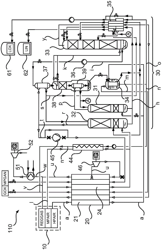
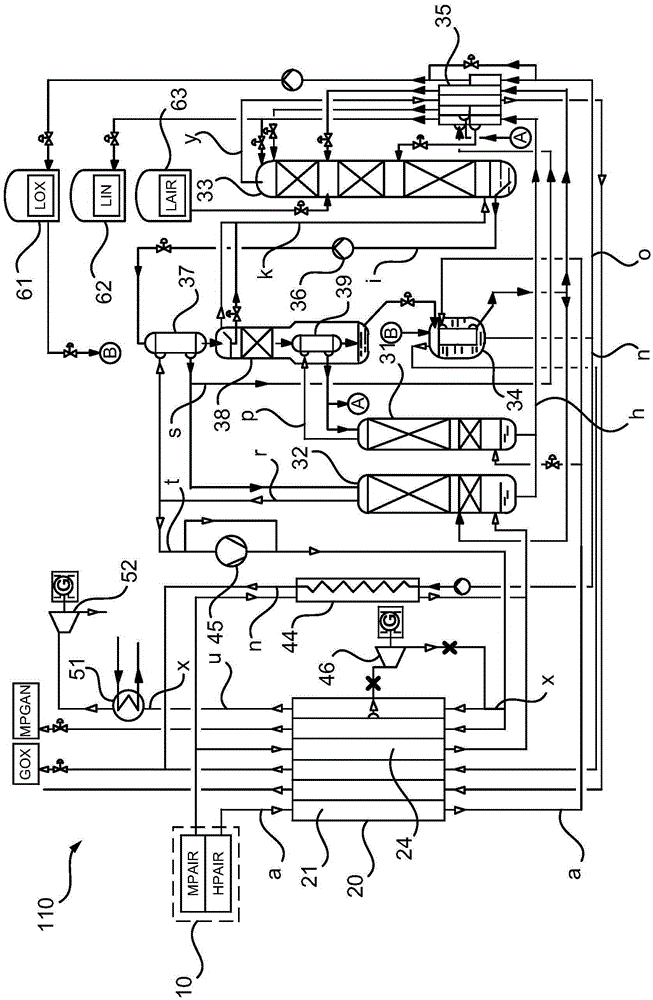
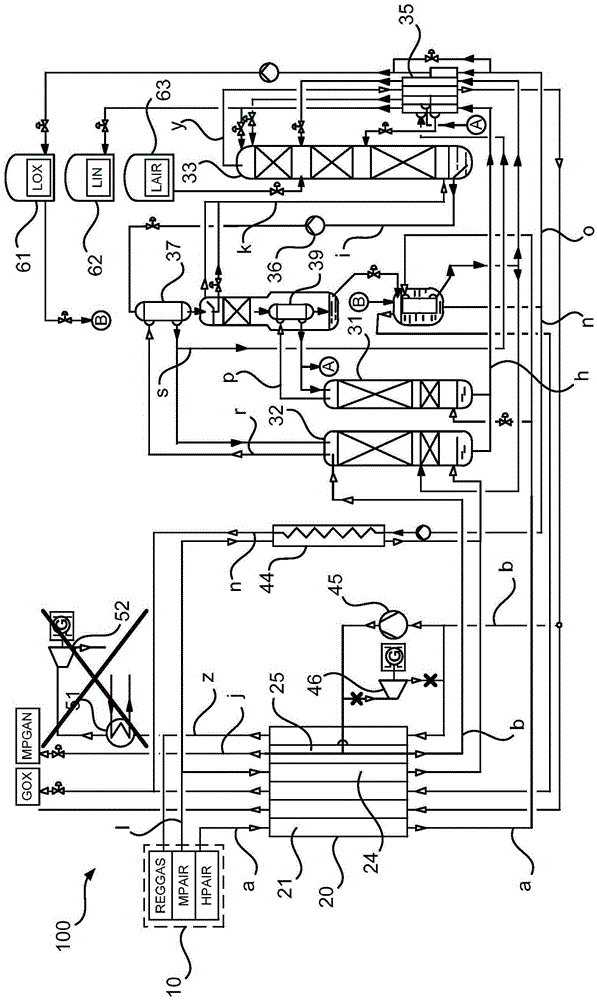
[0060] Equivalent components have the same symbols in the drawings and are not described repeatedly for brevity and clarity.

[0061] Figure 1 to Figure 10 Shown are icons of some of the same equipment and its components in different operating modes. The operating modes differ mainly in the position of multiple valves in the corresponding pipelines, so that liquid flow and gaseous flow pass through different equipment components. Valves are not shown. But the blocking line is crossed (-x-).

[0062] figure 1 It is a schematic diagram of an air separation plant 110 not of the present invention. The air separation plant 110 is in figure 1 In the first mode of operation, no substantial amount of liquid air product from an "external source" (such as a storage tank or an air liquefaction plant) is fed into the air separation plant. The icon first mode of operation is used, for example, to generate liquid air products during periods of low electricity prices or excess electric...


PUM


Abstract

The invention relates to a method for producing at least one air product, wherein an air separation system (100) is used which has a primary air compressor (10), a primary heat exchanger (20) and a distillation column system (30), and which comprises a first and a second operation mode, wherein, in the first operating mode, at least one liquid air product (LIN, LOX) produced in the distillation column system (30) is saved and, in the second operating mode, the at least one air product (LIN, LOX, LAIR) saved in the first operating mode and / or at least one additional liquid air product is supplied to the distillation column system (30). The method is characterized in that, in the second operating mode, at least one gaseous pressure flow (b - g) at a temperature level which lies below a hot-side temperature of the primary heat exchanger (20) is supplied to a cold compressor (45), compressed in the cold compressor (45) from a first above-atmospheric pressure level to a second above-atmospheric pressure level, and is supplied to at least one distillation column (31, 32) of the distillation column system (30) at the second above-atmospheric pressure level. The invention further relates to a corresponding air separation system (100) and to a method and to a device for producing electrical energy.

Description

technical field [0001] The invention relates to a method for producing at least one air product, an air separation plant and a method and a device for generating electrical energy according to the preambles of the independent claims. Background technique [0002] "Condensing evaporator" means a heat exchanger for indirect heat exchange between a first condensing fluid stream and a second evaporating fluid stream. All kinds of condensation evaporators have a liquefaction chamber and an evaporation chamber respectively composed of a liquefaction channel and an evaporation channel. The first fluid stream is condensed (liquefied) within the liquefaction chamber and the second fluid stream is evaporated within the evaporation chamber. The evaporating chamber and the liquefying chamber are formed by channel groups in heat exchange relationship with each other. The evaporation chamber of the condensing evaporator can be configured as a bath evaporator, falling film evaporator or ...

Claims


Application Information

Patent Timeline
Patent Type & Authority Applications(China)
IPC IPC(8): F25J3/04
CPCF25J3/04054F25J3/04084F25J3/0409F25J3/04412F25J3/04496F25J3/04836F25J2210/50F25J2210/40F25J2210/42F25J3/04878F25J3/04884F25J3/04048F25J3/0406F25J3/04206F25J3/04218F25J3/04224F25J3/0426F25J3/04303F25J3/04309F25J3/04448F25J3/04581F25J2200/34F25J2200/54F25J2235/50F25J2245/02F25J2245/42F25J2250/04F25J2250/40F25J2250/50F25J3/04018F25J3/04254F25J3/04321F25J2260/50
Inventor A·阿列克谢耶夫
Owner LINDE AG
Why Eureka
Try Eureka