Boiler roof expansion joint sealing device

A technology for expansion joints and corrugated expansion joints is applied in the field of boiler ceiling expansion joint sealing devices, which can solve the problems of affecting the safe operation of the heating surface and being easy to be pulled and cracked, and achieve the effects of simple structure, convenient workshop processing, and convenient on-site construction.

Active Publication Date: 2018-02-13
HARBIN BOILER
View PDF4 Cites 2 Cited by
  • Summary
  • Abstract
  • Description
  • Claims
  • Application Information

AI Technical Summary

Problems solved by technology

[0002] The furnace and flue of a large pulverized coal boiler are fully sealed. However, the sealing of the membrane wall arranged around the ceiling, the heating surface of the pipe passing through the ceiling, the suspender, and the pipe cannot be achieved if only steel plates are used. The free expansion between parts is easy to crack, which affects the safe operation of the heating surface. At present, the sealing structure of domestic power plant boilers is sealed with steel plates or bolted connections, and it is easy to crack at the corners of the steel plates.

Method used


Image

  • Boiler roof expansion joint sealing device
  • Boiler roof expansion joint sealing device
  • Boiler roof expansion joint sealing device

Examples


Embodiment 1

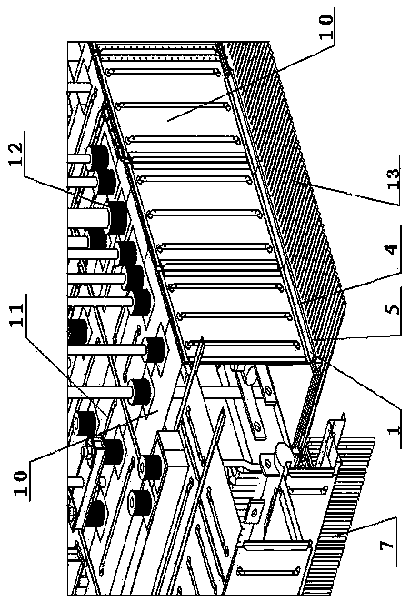
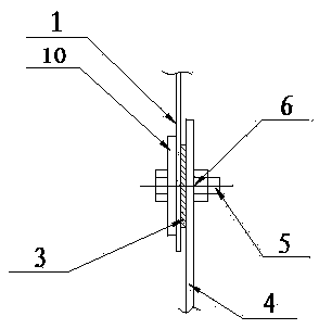
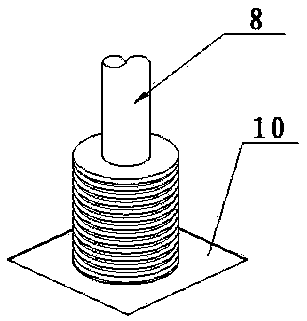
[0019] A boiler ceiling expansion joint sealing device, which consists of: ceiling pipe 13, guard plate 10, comb plate 4, corrugated expansion joint 1, circular expansion joint 12, pressure plate and ceramic fiber paper 3, the connection form is divided into ceiling film Type wall, surrounding membrane type wall, pipe 9 passing through furnace roof and suspender 8 are connected with the guard plate, and the ceiling membrane type wall and surrounding membrane type wall are connected with the guard plate by The comb-shaped plate is welded on the ceiling pipe and the water-cooled wall 7, the corrugated expansion joint is added between the guard plate and the comb-shaped plate, and the comb-shaped plate and the The ceramic fiber paper is placed between the corrugated expansion joints, and the corrugated expansion joints are welded to the guard plate.

Embodiment 2

[0021] According to the boiler ceiling expansion joint sealing device described in Example 1, the ceiling membrane wall and surrounding membrane walls are connected to the guard plate, which is a ceiling metal inner guard plate covering the header and pipe joints Solder connection is used between them.

Embodiment 3

[0023] According to the boiler ceiling expansion joint sealing device described in embodiment 1 or 2, the pipe connection through the furnace roof adopts the method of adding the circular expansion joint, that is, the pipe passes through the circular expansion joint , and one end of the circular expansion joint is welded to the guard plate, and the other end is welded to the pre-welded part of the pipeline.


PUM


Abstract

The invention relates to an expansion joint sealing device of a boiler ceiling. Conventional steel plate sealing cannot realize free expansion between components, and the components are easily pull-cracked. The expansion joint sealing device consists of ceiling pipes (13), guard plates(10), comb-shaped plates (4), ripple expansion joints (1), circular expansion joints (12), pressing plates (2) and ceramic fiber paper (3). Connection forms comprise that a ceiling membrane type wall, peripheral membrane type walls, and pipelines (9) and hanging rods (8), which penetrate through a furnace roof are connected with the guard plates, wherein the ceiling membrane type wall, and the peripheral membrane type walls are connected with the guard plates in the manner that the comb-shaped plates are welded to the ceiling pipes and a water-cooled wall (7), the ripple expansion joints are additionally arranged between the guard plates and the comb-shaped plates, and the ceramic fiber paper is padded between the comb-shaped plates and the ripple expansion joints; the ripple expansion joints and the guard plates are in welding connection. The expansion joint sealing device disclosed by the invention is applied to the expansion joint sealing device of the boiler ceiling.

Description

Technical field: [0001] The invention relates to a sealing structure between a large-scale pulverized coal boiler ceiling membrane wall, surrounding membrane walls, pipes passing through the furnace roof, and suspenders, in particular to a boiler ceiling expansion joint sealing device. Background technique: [0002] The furnace and flue of a large pulverized coal boiler are fully sealed. However, the sealing of the membrane wall arranged around the ceiling, the heating surface of the pipe passing through the ceiling, the suspender, and the pipe cannot be achieved if only steel plates are used. The free expansion between components is easy to crack, which affects the safe operation of the heating surface. At present, the sealing structure of domestic power plant boilers is sealed with steel plates or bolted connections, and it is easy to crack at the corners of the steel plates. Invention content: [0003] The object of the present invention is to provide a boiler roof expa...

Claims


Application Information

Patent Timeline
Patent Type & Authority Patents(China)
IPC IPC(8): F22B37/10
CPCF22B37/105
Inventor 赵彦华夏良伟郭建明乔丽英宋国庆
Owner HARBIN BOILER
Why Eureka
Try Eureka