Method and device for liquefying low-boiling-point gas and recovering BOG (Boil Off Gas) of cryogenic vessel

A low-temperature container, low boiling point technology, applied in liquefaction, refrigeration, liquefaction, solidification and other directions, can solve the problems of complex structure, difficult operation, high operating cost, and achieve the effects of low system energy consumption, reliable operation and simple process

Active Publication Date: 2016-03-09
京鼎工程建设有限公司
View PDF8 Cites 2 Cited by
  • Summary
  • Abstract
  • Description
  • Claims
  • Application Information

AI Technical Summary

Problems solved by technology

[0011] There are certain difficulties in the above methods and processes, or the structure is complex and expensive, or the operation is difficult, or the equipment is difficult to manufacture, or the operating cost is too high.

Method used


Image

  • Method and device for liquefying low-boiling-point gas and recovering BOG (Boil Off Gas) of cryogenic vessel
  • Method and device for liquefying low-boiling-point gas and recovering BOG (Boil Off Gas) of cryogenic vessel

Examples


Embodiment 1

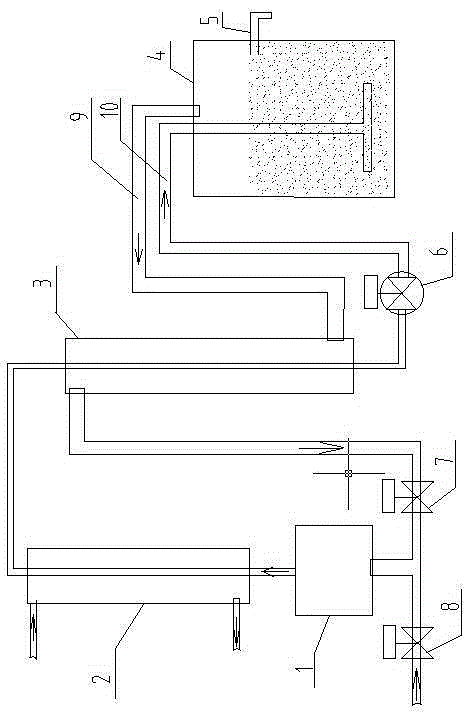
[0038] Example 1: Used in the liquefaction of natural gas.

[0039] see figure 1 , the compressor 1 is a normal temperature compressor; the conventional heat exchanger 2 is a water-cooled heat exchanger, and the shell side is cooling water; the subcooling heat exchanger 3 is a vertically installed tube-and-tube heat exchanger.

[0040] The medium-pressure high-temperature gas outlet of compressor 1 is connected to the tube-side inlet of conventional heat exchanger 2, and the tube-side outlet of conventional heat exchanger 2 is connected to the tube-side inlet of subcooling heat exchanger 3 (the tube-side inlet is located in the subcooling heat exchanger 3), the outlet of the tube side of the subcooling heat exchanger 3 is connected to the inlet of the throttling pressure reducer 6, and the throttling pressure reducer 6 uses a throttling control valve to reduce the outlet pressure to a lower pressure than that of the low temperature liquefaction storage tank 4 liquid The phase...

Embodiment 2

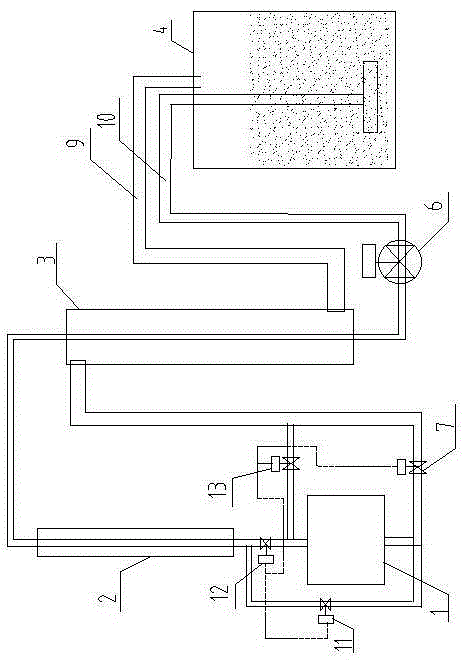
[0046] Example 2: BOG recovery for LNG storage tanks.

[0047] see figure 2 , the overall structure of the device is basically the same as that of Embodiment 1, the main difference being: no fresh air input, no fresh air control valve 8; There is an air flow pipeline connected between them and a first air flow control valve 11 is installed; a second air flow control valve 12 is installed at the air outlet of the compressor 1; An airflow pipeline is connected between the stroke outlets and a third airflow direction control valve 13 is installed.

[0048] Its basic working process is the same as that of Embodiment 1, mainly because the flow direction of the inlet and outlet airflow of compressor 1 can be switched, because this system is only used for the recovery and internal pressurization of the liquid evaporator gas (BOG) in the low-temperature liquefaction storage tank 4, Therefore, the overflow pipe 5 which plays a role in stabilizing the liquid level is also cancelled. ...


PUM


Abstract

The invention relates to a method and a device for liquefying low-boiling-point gas and recovering BOG (Boil Off Gas) of a cryogenic vessel. The method and the device are characterized in that low-pressure normal-temperature gas to be liquefied is compressed into medium-pressure gas through a compressor; the medium-pressure gas is cooled into medium-pressure normal-temperature gas through a common heat exchanger; then the medium-pressure normal-temperature gas is subjected to flyback heat exchanging with cryogenic gas which is pumped from a gas phase space of a cryogenic liquid vessel through an undercooling heat exchanger so as to obtain medium-pressure undercooling gas; the medium-pressure undercooling gas is subjected to throttling and pressure reduction to be further cooled; the cooled gas is charged into liquefied liquid in the cryogenic vessel to be mixed with the cryogenic liquid, and the gas can directly exchange heat with the cryogenic liquid and then be condensed so as to achieve liquefying; some non-condensed gas which absorbs the cold energy of the cryogenic liquid is pumped into the undercooling heat exchanger from the top part of the vessel; the normal-temperature medium-pressure gas is converted into normal-temperature gas after cooling and compressing; finally, the normal-temperature gas is charged into the compressor. The method and the device are applicable to BOG liquefying and recovering of the cryogenic vessel in case of no fresh gas, and fast pressurizing of the cryogenic vessel when the gas reversely flows. The method and the device are simple in process, low in cost, reliable to implement and run, and low in system energy consumption.

Description

technical field [0001] The invention relates to a method and a device for liquefying low-boiling point gas and recovering and pressurizing BOG in a low-temperature container, belonging to the technical fields of low-temperature refrigeration and low-temperature liquid production. Background technique [0002] When the gas whose critical temperature is lower than 50°C is liquefied, due to the low temperature of the liquefaction point, it is generally impossible to liquefy directly and simply by refrigeration. It often requires multi-stage compression and refrigeration and condensation with other media to achieve its final liquefaction. The process is often very complicated and the cost is high. high. [0003] At the same time, during the storage process of low-boiling liquefied gas, boil-off gas (BOG gas for short) will inevitably be produced. If this part of gas is not treated, it will increase the internal pressure of the cryogenic container and affect safety; but this BOG ...

Claims


Application Information

Patent Timeline
Patent Type & Authority Applications(China)
IPC IPC(8): F25J1/02
CPCF25J1/0201F25J1/0249F25J1/0254
Inventor 王连霞刘印同王树方
Owner 京鼎工程建设有限公司
Why Eureka
Try Eureka