Muffling device and electromechanical device

A technology for noise reduction devices and electromechanical equipment, which is applied in the field of electromechanical equipment and noise reduction devices, which can solve problems such as limited use, fading, corrosion, etc., and achieve the effects of improving usage conditions, widening audio bandwidth, and widening application fields

Pending Publication Date: 2016-03-09
GREE ELECTRIC APPLIANCES INC
View PDF6 Cites 6 Cited by
  • Summary
  • Abstract
  • Description
  • Claims
  • Application Information

AI Technical Summary

Problems solved by technology

[0006] First, the micropores on the thin plate are easily blocked by flying dust, which affects the sound absorption effect and requires frequent maintenance;
[0007] Second, thin plates are easily deformed, corroded and faded;
[0008] Third, the sound absorption coefficient for low and high-frequency noise sections is low, and the overall sound absorption frequency bandwidth is not large. Although the frequency bandwidth can be increased by using a double-layer micro-hole perforated plate, a thicker cavity is required, from which Structural and economical considerations are inappropriate;
[0009] Fourth, the "air cushion spring" after perforation is too thick, which limits its use in occasions with space requirements
[0010] In addition, CN912088222 discloses a combined high-efficiency muffler, whose structure is composed of a sound reflection cone and surrounding sound-absorbing materials. Although this kind of muffler can effectively absorb vertical noise, the inventors of the present invention found that due to its structure and sound-absorbing The limitation of the principle makes it have the following disadvantages: first, it cannot be made thin; second, it cannot be used in wide-plane sound-absorbing occasions; third, its internal sound-absorbing material limits its work in high-temperature, humid and dusty environments
[0011] In summary, due to the above defects in the above-mentioned existing muffler, its application on electromechanical equipment is limited

Method used


Image

  • Muffling device and electromechanical device
  • Muffling device and electromechanical device
  • Muffling device and electromechanical device

Examples


Embodiment 1

[0049]On the one hand, this embodiment provides a noise reduction device, which is used in electromechanical equipment that is prone to noise (such as air conditioning equipment) to eliminate the noise generated when the working parts in the electromechanical equipment are running, so as to improve people's life or life. Work creates a better environment.

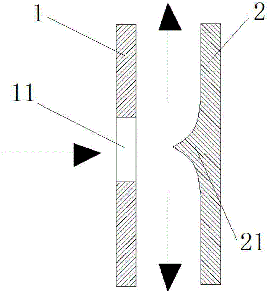
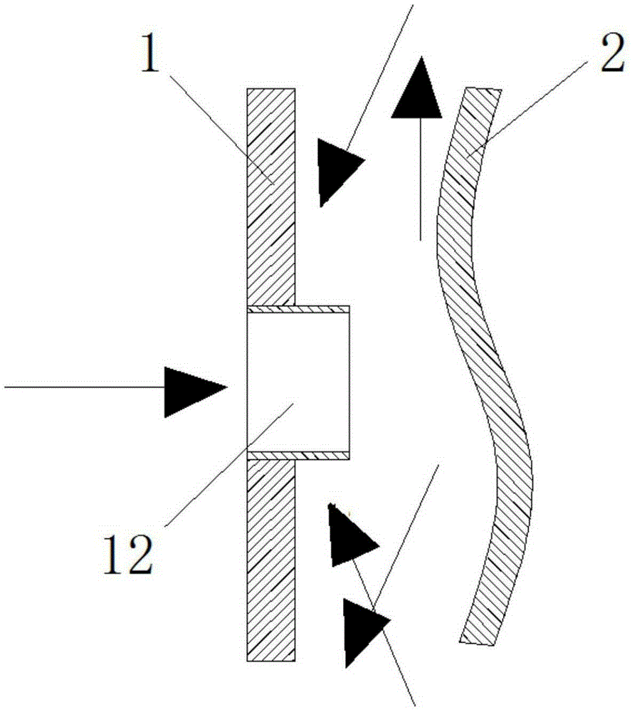
[0050] Specifically, such as figure 1 and figure 2 As shown, the muffler is a closed cavity structure. Wherein, the noise reduction device includes a first side plate 1 and a second side plate 2 . Wherein, the first side plate 1 is provided with a plurality of holes 11 . The second side plate 2 is arranged opposite to the first side plate 1; and the second side plate 2 and the first side plate 1 form two opposite side walls of the airtight cavity. Wherein, the plurality of holes 11 on the first side plate 1 are used to allow beam-shaped sound waves to enter the airtight cavity through the small holes. Wherein, the sec...

Embodiment 2

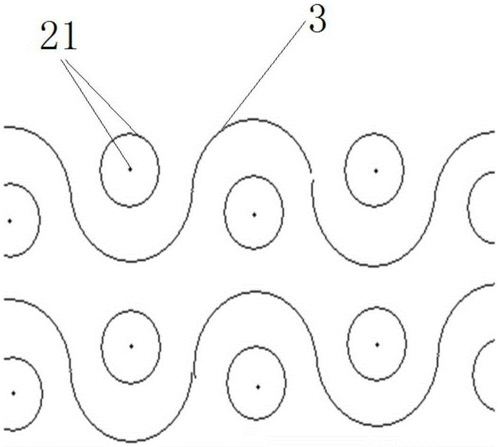
[0056] Preferably, this embodiment provides a noise reduction device, compared with Embodiment 1, such as figure 1 As shown, the second side plate 2 of the noise reduction device in this embodiment includes a second side plate body and a sound guide part 21 . Wherein, the second side plate body is a flat plate structure. The number of the sound guides 21 is consistent with the number of the holes 11 , and they are arranged at positions corresponding to the holes 11 on the second side plate body. Wherein, the sound guide part 21 is used to change the propagation direction of the beam-shaped sound wave vertically entering the small hole, so that it can diverge and propagate along the direction of the plane where the second side plate body is located, and finally make the sound wave travel along the plane where the second side plate body is located. Under the damping action of the "air cushion spring" in the direction, it is gradually converted into internal energy and dissipate...

Embodiment 3

[0062] Preferably, this embodiment provides a noise reduction device, compared with Embodiment 2, such as figure 1 As shown, the sound guide part 21 in this embodiment has a first end and a second end opposite to each other. Wherein, the first end of the sound guide part 21 is arranged on the second side plate 2 , and the second end of the sound guide part 21 is arranged to point to the tip of the corresponding hole 11 .

[0063] Preferably, the sound guide part 21 is a cone structure, and the generatrix of the cone is a curve, and the curve is preferably a parabola, so as to better convert the sound wave vertically incident into the cavity from the hole 11 into the sound wave along the second side plate body. Sound waves that spread out in a plane. Wherein, the first end of the sound guiding part 21 is the bottom surface of the cone structure, and the second end of the sound guiding part 21 is the top of the cone structure.

[0064] The sound-absorbing device provided in th...


PUM


Abstract

The invention relates to a muffling device and an electromechanical device and belongs to the muffling technical field. According to the main technical schemes of the invention, the muffling device is of a sealed cavity structure; the muffling device includes a first side plate and a second side plate; a plurality of holes are formed in the first side plate and used for enabling beam-shaped acoustic waves to enter a sealed cavity; the first side and the second side plate are oppositely arranged; and the second side plate is set to a sound guiding structure and is used for changing the transmission direction of the beam-shaped acoustic waves entering the sealed cavity so as to enable the beam-shaped acoustic waves to be transmitted divergently in the sealed cavity, so that the acoustic waves can be converted into inner energy gradually under damping effects in divergent transmission directions. The electromechanical device comprises the above muffling device, so that noises generated by the electromechanical device can be removed. According to the muffling device provided by the invention, noises can be removed, and the thickness of the muffling device can be decreased, and the use condition of the muffling device in the limited space of the electromechanical device can be improved.

Description

technical field [0001] The invention relates to the technical field of noise reduction, in particular to a noise reduction device and electromechanical equipment with the noise reduction device. Background technique [0002] The noise emitted by electromechanical equipment will bring noise pollution to people's life and work. [0003] Taking air-conditioning equipment as an example, when the air-conditioning equipment is running, the noise generated by the fan on it escapes into the room, the regenerative noise at the end of the air pipe, and the noise generated when the compressor is working, etc. Here comes the trouble. In order to reduce the noise during the operation of the air-conditioning equipment, sound-absorbing cotton is usually pasted on the partitions in the air-conditioning equipment. However, the existing large-capacity side-outlet multi-line partition is a single-layer sheet metal part, which has no noise-absorbing function. Since multiple welding and hot-fi...

Claims


Application Information

Patent Timeline
Patent Type & Authority Applications(China)
IPC IPC(8): G10K11/16G10K11/162G10K11/02F24F13/24
CPCG10K11/02G10K11/161G10K11/162F24F13/24F24F2013/247G10K2210/118
Inventor 魏亮
Owner GREE ELECTRIC APPLIANCES INC
Why Eureka
Try Eureka