
Cylinder-shaped primary permanent magnet type transverse flux linear motor

A technology of transverse magnetic flux and linear motor, applied in the direction of magnetic circuit shape/style/structure, electrical components, electromechanical devices, etc., can solve problems such as high power density and thrust density, low primary space utilization rate, and difficult manufacturing process , to achieve the effects of easy heat dissipation, high utilization of primary space, and low manufacturing cost

Active Publication Date: 2016-03-09
NANJING UNIV OF AERONAUTICS & ASTRONAUTICS
View PDF4 Cites 8 Cited by
  • Summary
  • Abstract
  • Description
  • Claims
  • Application Information

AI Technical Summary

Problems solved by technology

[0003] The traditional permanent magnet linear motor has an axial magnetic circuit structure, the magnetic load and thermal load are cross-coupled, and the power density is low; while the magnetic load and thermal load of the transverse flux permanent magnet linear motor are decoupled, the power density and thrust density are higher than those of the traditional permanent magnet Linear Motor High
[0004] Although the power density and thrust density of traditional permanent magnet transverse flux linear motors are higher than those of traditional permanent magnet linear motors, there is still a lot of room for improvement in power density, and there are complex structures, difficult manufacturing processes, and low primary space utilization. , The problem of high secondary inertia

Method used


Image

  • Cylinder-shaped primary permanent magnet type transverse flux linear motor
  • Cylinder-shaped primary permanent magnet type transverse flux linear motor
  • Cylinder-shaped primary permanent magnet type transverse flux linear motor

Examples


Embodiment Construction

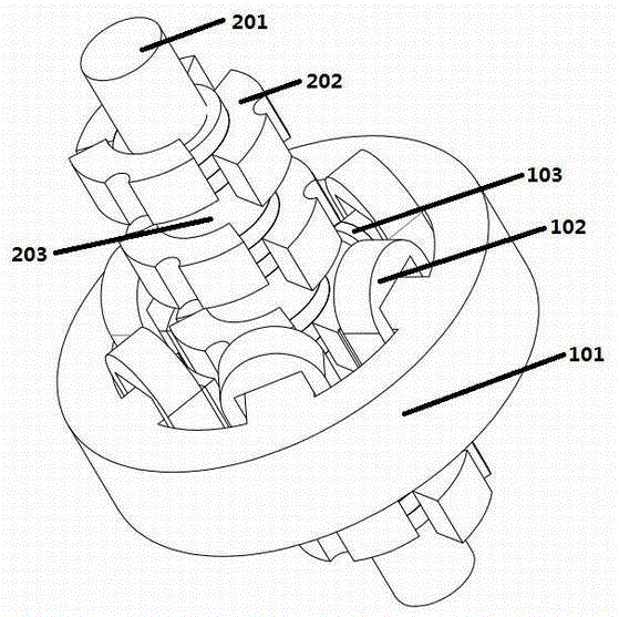
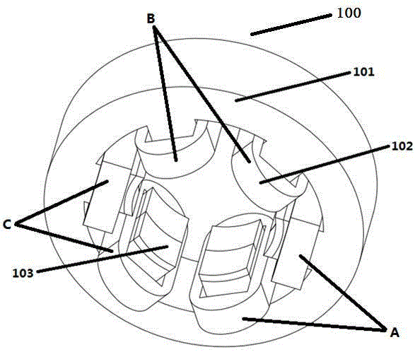
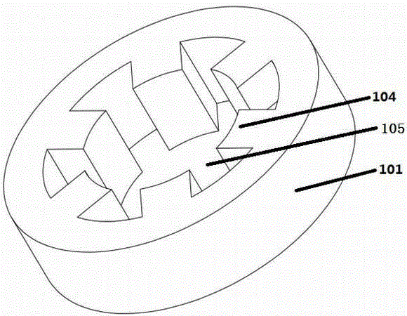
[0033] The present invention provides an open cylindrical primary permanent magnet type transverse flux linear motor. In order to make the purpose, technical solution and effect of the present invention clearer and clearer, the present invention will be further described in detail with reference to the accompanying drawings and examples. It should be understood that the specific implementations described here are only used to explain the present invention, not to limit the present invention.

[0034] Below, refer to Figure 1 to Figure 11 , taking the number of unit motor phases m=3, the number of pole pairs p=1, and n=1 as an example, the cylindrical primary permanent magnet transverse flux linear motor involved in the present invention will be described in detail.

[0035] Such as Figure 1 to Figure 5 As shown, a cylindrical primary permanent magnet transverse flux linear motor provided by the present invention includes a permanent magnet primary 100 and a secondary 200; t...


PUM


Abstract

The present invention discloses a cylinder-shaped primary permanent magnet type transverse flux linear motor, comprising a permanent magnet type primary and a secondary; wherein the permanent magnet type primary comprises a stator core, an armature winding and permanent magnets; the stator core is in an annular shape, the inner surface of the stator core is provided with stator core teeth which are arranged uniformly, armature winding coils are wound on the stator core teeth, the permanent magnets are installed to the end surfaces of the stator core teeth, and the magnetizing direction of the permanent magnet is radial; the secondary comprises a shaft, magnet separation rings and a rotor core; a plurality of layers of rotor core rings are uniformly distributed along the axial direction, the rotor core rings are separated by the magnet separation rings; each layer of rotor core ring is formed in the way that a plurality of special-shaped fan-shaped rotor cores are staggered at a certain angle successively along the circumferential direction, and the adjacent rotor cores are staggered at a certain distance along the axial direction. The cylinder-shaped primary permanent magnet type transverse flux linear motor of the present invention solves the problems of complex structure, high manufacturing process difficulty, low primary space utilization rate, high secondary inertia, and low power density of a conventional cylinder-shaped transverse flux linear motor.

Description

technical field [0001] The invention relates to a cylindrical primary permanent magnet type transverse magnetic flux linear motor, which belongs to the technical field of linear motors. Background technique [0002] Linear motors directly convert electrical energy into mechanical energy for linear motion, eliminating the need for redundant mechanical transmission mechanisms in the middle. The system has high efficiency, fast response, low noise, and easy maintenance, so it is widely used in the field of linear motion. [0003] The traditional permanent magnet linear motor has an axial magnetic circuit structure, the magnetic load and thermal load are cross-coupled, and the power density is low; while the magnetic load and thermal load of the transverse flux permanent magnet linear motor are decoupled, the power density and thrust density are higher than those of the traditional permanent magnet The linear motor is high. [0004] Although the power density and thrust densi...

Claims


Application Information

Patent Timeline
Patent Type & Authority Applications(China)
IPC IPC(8): H02K41/03H02K1/17H02K1/24
CPCH02K1/17H02K1/24H02K41/033
Inventor 董顶峰黄文新卜飞飞张宇王齐王乐
Owner NANJING UNIV OF AERONAUTICS & ASTRONAUTICS
Learn More