
Hydrogen recycling apparatus and method of operation

一种氢气、反应气体的技术,应用在电化学系统领域,能够解决升高、升高功率消耗等问题

Active Publication Date: 2016-03-09
SKYRE INC
View PDF7 Cites 0 Cited by
  • Summary
  • Abstract
  • Description
  • Claims
  • Application Information

AI Technical Summary

Problems solved by technology

However, increasing the voltage applied to the battery at any time increases the power consumption

Method used


Image

  • Hydrogen recycling apparatus and method of operation
  • Hydrogen recycling apparatus and method of operation
  • Hydrogen recycling apparatus and method of operation

Examples


Embodiment Construction

[0019] Embodiments of the present invention provide the advantage of separating hydrogen from gas streams that include pollutants (eg, CO). Embodiments of the present invention provide the advantage of rejuvenating the catalyst in the electrochemical cell to allow operation of the electrochemical cell at high CO concentrations. Further embodiments of the invention provide the advantage of allowing operation of fuel cells on gas streams with CO.

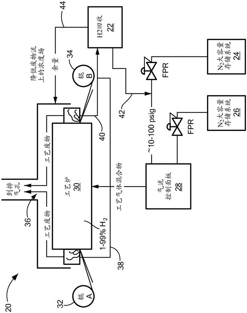
[0020] Now refer to the attached figure 1 , shows an exemplary process 20 having an electrochemical hydrogen recovery device 22 . Process 20 typically includes a bulk hydrogen storage system 24 and a bulk nitrogen storage system 26 . Gases from storage system 24 , storage system 26 are combined to manifolds on airflow control panel 28 . The gas flow control panel 28 is configured to flow a desired volume of the gas mixture to a process device, such as a furnace 30 . In the case where the process device is a furnace 30, the materi...


PUM


Abstract

A method of operating an electrochemical cell stack is provided. The method includes feeding a reactant gas to the cell stack. The flow of the reactant gas is halted to at least one cell in the cell stack. The voltage applied to the at least one cell is increased. The flow of reactant gas to the at least one cell is initiated in response to the voltage increasing above a threshold for a predetermined amount of time.

Description

[0001] Cross References to Related Applications [0002] This application is a non-provisional application of US Provisional Application Serial No. 61 / 829,478, filed May 31, 2013, entitled "Hydrogen Recycling Apparatus and Method of Operation," the contents of which are incorporated herein by reference. technical field [0003] The subject matter disclosed herein relates to electrochemical systems for separating hydrogen from pollutants in a gas stream consisting primarily of hydrogen, and more particularly to an electrochemical system for separating hydrogen from a mixture containing carbon monoxide ("CO") pollutants. system. Background technique [0004] Polymer Electrode Membrane ("PEM") systems use an electrochemical process to separate hydrogen from other elements or compounds. An example of a PEM system is a stack of electrolysis cells, which split water into hydrogen and oxygen. Another type of PEM system can be used to generate hydrogen from hydrogen and other com...

Claims


Application Information

Patent Timeline
Patent Type & Authority Applications(China)
IPC IPC(8): C25B1/04C25B9/10C25B9/23
CPCC01B3/50C21D1/74B01D2256/16B01D2257/502B01D2258/02C01B3/16C25B1/02H01M8/0606H01M8/0681B01D53/326Y02E60/36Y02P10/20Y02E60/50C25B1/04C25B9/73
Inventor 乔舒亚·S·普勒斯顿
Owner SKYRE INC
Learn More