
Stirring equipment for chemical industry detection

A stirring equipment and chemical technology, applied in the direction of mixer accessories, mixers with rotating stirring devices, chemical instruments and methods, etc., can solve the problems of the mixer's thermal insulation and service life is not very high, uneven mixing, etc., to achieve reliable High performance, good stability, and the effect of improving efficiency

Inactive Publication Date: 2016-03-16
郑臣钏
View PDF4 Cites 0 Cited by
  • Summary
  • Abstract
  • Description
  • Claims
  • Application Information

AI Technical Summary

Problems solved by technology

[0002] At present, stirring equipment is widely used in the production of chemical industry to prepare homogeneous mixtures; to promote mass transfer (such as dissolution, crystallization, gas absorption, etc.); to promote heat transfer (heating or cooling in reactors, etc.); Make the substances participating in the reaction in good contact, improve the reaction efficiency, control the reaction temperature, etc. In the fluid medium, the commonly used stirring method is mechanical stirring, which is realized by using various types of impellers on the stirring shaft. The current stirring The thermal insulation and service life of the device are not very high. In addition, sometimes temperature control is required during stirring, and heating is required in this process, but there is basically no such equipment on the market now. In addition, traditional stirring generally increases Stirring speed can further improve the stirring efficiency. This method has uneven stirring, so a stirring equipment for chemical testing is needed to solve the above problems.

Method used


Image

  • Stirring equipment for chemical industry detection
  • Stirring equipment for chemical industry detection
  • Stirring equipment for chemical industry detection

Examples


Embodiment Construction

[0017] The following will clearly and completely describe the technical solutions in the embodiments of the present invention with reference to the accompanying drawings in the embodiments of the present invention. Obviously, the described embodiments are only some, not all, embodiments of the present invention. Based on the embodiments of the present invention, all other embodiments obtained by persons of ordinary skill in the art without making creative efforts belong to the protection scope of the present invention.

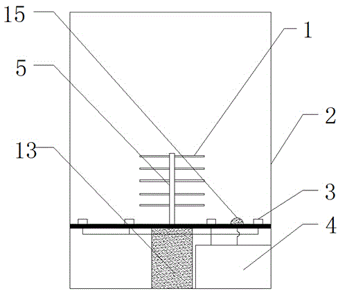
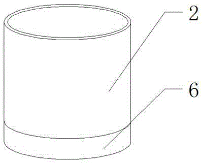
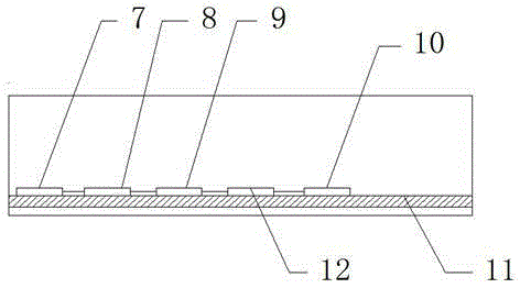
[0018] see Figure 1-5 , the present invention provides a technical solution: a stirring device for chemical testing, including a main part of the stirring device and a control part, the main part of the stirring device consists of a stirring paddle 1, a stirring drum 2, an electromagnetic heating tube 3, a rotating shaft 5, and a fixing seat 6 , a vertical rod 14 and a drive motor 13, the fixed seat 6 is arranged parallel to the horizontal plane, the upper en...


PUM


Abstract

The invention discloses stirring equipment for chemical industry detection. An electromagnetic heating pipe is located on a bottom end surface of the inner side of a stirring barrel; a wireless receiving module is in one-way electrical connection with an analog-digital converter; the analog-digital converter is in one-way electrical connection with an embedded central processing unit; a temperature sensor is mounted on the bottom end surface of the inner side of the stirring barrel. A drive motor and the electromagnetic heating pipe are wirelessly controlled due to addition of the wireless receiving module and a wireless transmitting module, the purpose of long-range control is achieved due to addition of a control terminal; the heating problem of a stirred object is solved through the electromagnetic heating pipe; on one hand, the temperature is controlled, on the other hand, the stirring efficiency is improved, finally, the temperature is monitored in real time due to addition of the temperature sensor, and the problem that the stirred object is bonded to the inside of the stirring barrel and cannot be poured out is solved through acrylic acid.

Description

technical field [0001] The invention relates to the field of chemical equipment, in particular to a stirring equipment for chemical testing. Background technique [0002] At present, stirring equipment is widely used in the production of chemical industry to prepare homogeneous mixtures; to promote mass transfer (such as dissolution, crystallization, gas absorption, etc.); to promote heat transfer (heating or cooling in reactors, etc.); Make the substances participating in the reaction in good contact, improve the reaction efficiency, control the reaction temperature, etc. In the fluid medium, the commonly used stirring method is mechanical stirring, which is realized by using various types of impellers on the stirring shaft. The current stirring The thermal insulation and service life of the device are not very high. In addition, sometimes temperature control is required during stirring, and heating is required in this process, but there is basically no such equipment on th...

Claims


Application Information

Patent Timeline
IPC IPC(8): B01F7/20B01F15/06B01F27/906
Inventor 郑臣钏
Owner 郑臣钏
Learn More