Stamping and welding formation method for BFe 30-1-1 iron white copper small curvature radius elbow

A forming method, stamping welding technology, applied in the field of stamping welding forming, can solve problems such as wrinkles and fractures, and achieve the effects of easy operation, energy saving, and significant economic benefits

Inactive Publication Date: 2016-03-16
HARBIN TURBINE
View PDF6 Cites 1 Cited by
  • Summary
  • Abstract
  • Description
  • Claims
  • Application Information

AI Technical Summary

Problems solved by technology

[0007] The purpose of the present invention is to solve the problem that the small curvature radius elbow of BFe30-1-1 (iron-nickel-nickel) material is easy to produc

Method used


Image

  • Stamping and welding formation method for BFe 30-1-1 iron white copper small curvature radius elbow
  • Stamping and welding formation method for BFe 30-1-1 iron white copper small curvature radius elbow
  • Stamping and welding formation method for BFe 30-1-1 iron white copper small curvature radius elbow

Examples


specific Embodiment approach 1

[0041] Specific Embodiment 1: The stamping and welding forming method of a BFe30-1-1 iron-nickel-nickel elbow with a small radius of curvature in this embodiment is specifically prepared according to the following steps:

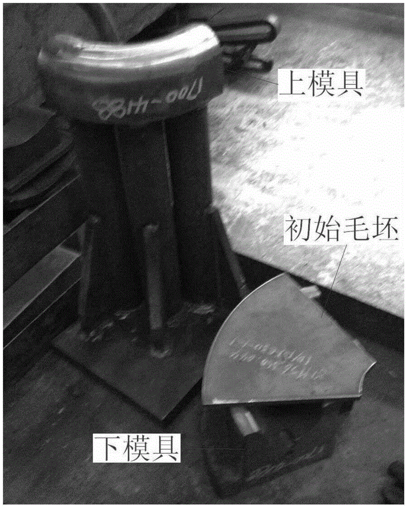
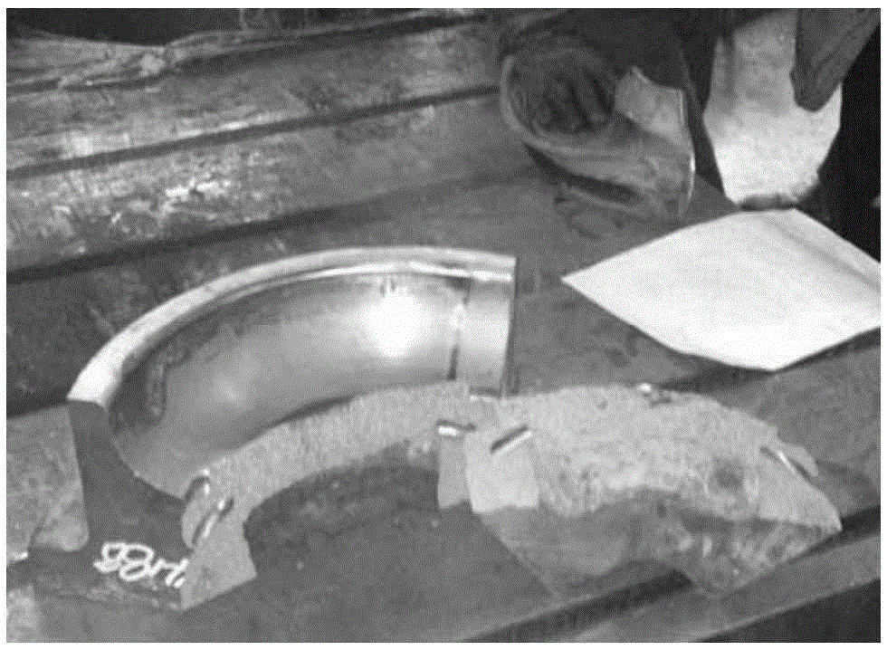
[0042] The plate is cold stamped into two half-rings butt joints. The test is carried out at room temperature, and edge material accumulation occurs, causing the mold to break (such as figure 2 shown);

[0043] During the forming process of the pipe fittings, the inner arc is squeezed and shrinks inward, and the outer arc is stretched and extended outward. figure 2 There are certain problems in the selection of raw materials as shown. Material accumulation occurs at the inner arc where the inner arc is squeezed, which causes the inner arc of the tooling to be subjected to a large extrusion force, causing the mold to break and the parts to be formed are not in place;

[0044] Step 1. Increase the chamfering radius r of the fillet of the lower die of the stam...

specific Embodiment approach 2

[0069] Embodiment 2: This embodiment differs from Embodiment 1 in that: in step 1, the radius r of the lower mold is increased to 13 mm or 14 mm. Other steps and parameters are the same as those in Embodiment 1.

specific Embodiment approach 3

[0070] Embodiment 3: The difference between this embodiment and Embodiment 1 or 2 is that in step 1, through analysis, it is known that the gap between the mold and the blank is too small, which causes the molding to make the blank go down smoothly, and the mold is redesigned, and the redesigned mold increases In order to improve the hardness, the stamping die is made of No. 45 steel plate, and the hardness is relatively high; among them, the hardness of the original mold is 230-280HBW, and the hardness of No. 45 steel plate is 480-600HBW. Other steps and parameters are the same as those in Embodiment 1 or Embodiment 2.


PUM

PropertyMeasurementUnit
Radiusaaaaaaaaaa
Hardnessaaaaaaaaaa
Hardnessaaaaaaaaaa

Abstract

The invention relates to a stamping and welding formation method, and particularly relates to a stamping and welding formation method for a BFe 30-1-1 iron white copper small curvature radius elbow. In order to solve the problems of high probability of wrinkles and breakage phenomenon caused by direct bending due to the small curvature radius of the BFe 30-1-1 iron white copper small curvature radius elbow, the invention provides the stamping and welding formation method for the BFe 30-1-1 iron white copper small curvature radius elbow. The method is achieved through the following steps: 1, using a steel plate No.45 to make a stamping die; 2, increasing a die-input round corner of a lower die; 3, designing a groove with a radius R of 25 to 30 mm in the middle part of the inner arc of a blank, so as to obtain a designed blank; 4, stamping the designed blank into two semicircular elbows; and 5, fitting up and welding the two semicircular elbows to form a circular elbow. The stamping and welding formation method provided by the invention is applicable to the field of stamping and welding formation.

Description

technical field [0001] The invention relates to a stamping welding forming method, in particular to a stamping welding forming method of a BFe30-1-1 iron-nickel nickel elbow with a small curvature radius. Background technique [0002] Due to the small radius of curvature of BFe30-1-1 (iron-nickel-copper) elbow, it is basically equal to its diameter, and direct bending is prone to wrinkles and fractures, which is difficult to achieve; due to BFe30-1-1 (iron-nickel-nickel) It is a special material, and there is no suitable standard elbow on the market. [0003] Stamping and welding forming refers to the use of a sheet material of the same material as the pipe to be stamped into a half-ring elbow with a stamping die, and then two half-ring elbows are paired and welded to form. In the prior art, stamping elbows are made of carbon steel, stainless steel, alloy steel and other materials, and there is no application of BFe30-1-1 (iron-nickel-nickel) material in this technology. ...

Claims


Application Information

Patent Timeline
IPC IPC(8): B23P15/00B21D37/10B21D22/02
CPCB23P15/00B21D22/02B21D37/10
Inventor 高作为刘俊峰王莉莉徐翔陈旭良于龙孙磊李宝磊谭延宏刘宇
Owner HARBIN TURBINE
Why Eureka
Try Eureka