Hydrodynamic pressure suspension polishing device with machining clearance capable of being adjusted

A technology of processing gap and polishing device, which is applied in the field of polishing, can solve problems such as low processing efficiency, non-adjustable processing gap, and difficulty in ensuring surface quality, and achieve high processing efficiency, low equipment cost, and uniform distribution of hydraulic pressure

Active Publication Date: 2016-03-16
ZHEJIANG UNIV OF TECH
View PDF5 Cites 11 Cited by
  • Summary
  • Abstract
  • Description
  • Claims
  • Application Information

AI Technical Summary

Problems solved by technology

[0005] In order to solve the problems of the existing non-contact polishing device, such as non-adjustable processing gap, low processing efficiency and difficult to guarantee the surface quality after processing, the present invention proposes a hydraulic suspension polishing device with adjustable processing gap, which can provide initial position adjustment , ...

Method used


Image

  • Hydrodynamic pressure suspension polishing device with machining clearance capable of being adjusted
  • Hydrodynamic pressure suspension polishing device with machining clearance capable of being adjusted
  • Hydrodynamic pressure suspension polishing device with machining clearance capable of being adjusted

Examples


Embodiment Construction

[0026] In order to make the object, technical solution and advantages of the present invention clearer, the present invention will be further described in detail below in combination with specific embodiments and with reference to the accompanying drawings. It should be understood that these descriptions are exemplary only, and are not intended to limit the scope of the present invention. Also, in the following description, descriptions of well-known structures and techniques are omitted to avoid unnecessarily obscuring the concept of the present invention.

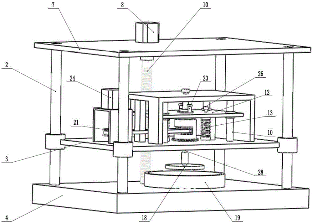
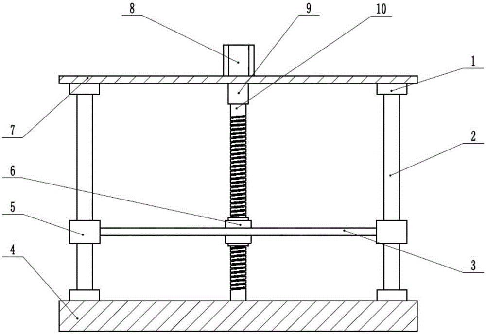
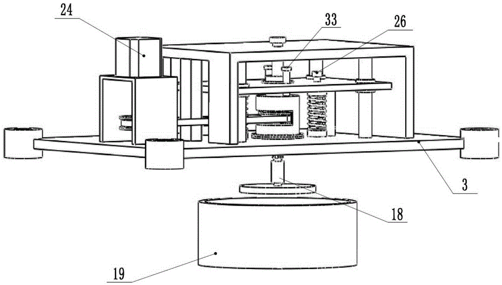
[0027] Such as figure 1 Shown is a schematic diagram of the polishing device of the present invention, which mainly includes two parts: a lifting part and a polishing part. Such as figure 2 Shown is the lifting part of the present invention, the rolling guide rail 2 is connected with the upper cover plate 7 and the base 4 through the support seat 1, the support plate 3 is connected with the sliding bushing 5 of the rol...


PUM


Abstract

The invention provides a hydrodynamic pressure suspension polishing device with a machining clearance capable of being adjusted. The polishing device comprises a lifting part and a polishing part. The lifting part mainly comprises rolling guide rails, a ball screw, a base, a middle supporting plate, an upper cover plate and a stepper motor. The stepper motor transmits torque through the ball screw to drive the middle supporting plate to go up and down. The polishing part mainly comprises a polishing disk, a ball spline shaft, springs, fine tuning knobs, a movable plate, a middle supporting plate, a guide rail, a servo motor and the like. The servo motor enables the polishing disk to rotate at a high speed through a belt wheel. The weight of the movable plate, the weight of the ball spline shaft and the weight of the polishing disk are overcome by the springs. The distance between the polishing disk and a container is adjusted through the fine tuning knobs. When the hydrodynamic pressure is increased, the polishing disk, the ball spline shaft and the movable plate float upwards overall, and when the hydrodynamic pressure is decreased, the polishing disk, the ball spline shaft and the movable plate descend overall, so that the adaptive suspension of the polishing disk during polishing is achieved. The movement of the movable plate is limited through a limiting threaded rod, and thus the fixed clearance is machined. According to the hydrodynamic pressure suspension polishing device, the machining efficiency is improved, and meanwhile the adjustability of the machining clearance is achieved.

Description

technical field [0001] The invention relates to the field of polishing, and provides a hydraulic suspension polishing device, which is mainly used in the fields of optics, electronics, information and communication, and the like. Background technique [0002] With the development of nanotechnology, the design and manufacture of micro-electromechanical systems are increasing, and the manufacturing technology and processing technology have entered the atomic and molecular nano-level from the sub-micron level. Breakthroughs in many new fields of science and technology have put forward higher requirements for nano-films and their preparation methods. The commonly used nano-film preparation methods, whether physical vapor deposition, chemical vapor deposition or electrodeposition, require an atomically ultra-smooth surface as a substrate for the growth of the film. [0003] Polishing is the main way to obtain atomic-level ultra-smooth substrates. Among them, the non-contact poli...

Claims


Application Information

Patent Timeline
IPC IPC(8): B24B1/00B24B47/12B24B41/00
CPCB24B1/00B24B41/007B24B47/12
Inventor 文东辉孙白冰蔡东海王扬渝章少杰
Owner ZHEJIANG UNIV OF TECH
Why Eureka
Try Eureka