Slide vane compressor

A compressor and sliding vane technology, which is applied in the field of compressors, can solve problems such as unstable pressure difference, increased power consumption, unfavorable sliding vane 99 protruding, etc., to ensure followability, reduce power consumption, and reduce sliding vane The effect of head power consumption

Active Publication Date: 2016-03-16
ZHUHAI GREE REFRIGERATION TECH CENT OF ENERGY SAVING & ENVIRONMENTAL PROTECTION
View PDF6 Cites 19 Cited by
  • Summary
  • Abstract
  • Description
  • Claims
  • Application Information

AI Technical Summary

Problems solved by technology

[0005] 1. If Figure 10 , because the power supplied by the back pressure oil is generated by the pressure difference between the high exhaust pressure above the oil pool 923 and the medium pressure of the back pressure oil groove 95, and the back pressure oil groove 95 communicates with the sliding vane groove 981, and the sliding vane is in the sliding vane groove 981 The telescopic movement will cause the volume of the tail chamber 982 of the slide groove 981 to change continuously, that is, the pressure in the tail chamber 982 of the slide groove 981 is in the process of changing, which will cause the pressure difference to be unstable. When the pressure difference is insufficient, it will Insufficient back pressure oil supply;
[0006] 2. If Figure 10 , the back pressure oil passage 93 is set on the lower bearing 961, limited by the outer diameter of the lower bearing 961, the inlet of the back pressure oil passage 93 will be at a certain distance from the oil pool 923, when the oil in the housing 921 enters the system, the inside of the housing 921 The oil level is low, which will cause the inlet of the back pressure oil channel 93 to be above the oil level, resulting in the inability to supply the back pressure oil;
However, due to the small compression rate of the oil, almost no compression, this design will cause excessive back pressure, resulting in severe friction between the head of the slide plate 99 and the cylinder 97 at this time;
[0008] 4. In this structure, the back pressure oil groove 95 provides high-pressure oil close to the exhaust pressure in almost the entire operating cycle of the slide plate 99 (except the exhaust position), and in the suction stage due to the gas force received by the head of the slide plate 99 Is the suction pressure. At this time, the tail of the slide plate 99 does not need too much back pressure, which will increase the friction of the head of the slide plate 99, resulting in increased power consumption;
[0009] 5. In the starting stage of the compressor, due to the small space of the back pressure oil passage 93, the negative pressure in the tail chamber 982 of the sliding vane groove 981 caused by the protruding of the sliding vane 99 does not have enough remaining gas to supplement, resulting in slippage during startup. The negative pressure in the tail chamber 982 of the slice groove 981 is not conducive to the extension of the slide plate 99 when the compressor is just started, and cannot guarantee the followability of the slide plate 99

Method used


Image

  • Slide vane compressor
  • Slide vane compressor
  • Slide vane compressor

Examples


Embodiment Construction

[0042] The present invention is described below based on examples, but the present invention is not limited to these examples. In the following detailed description of the invention, some specific details are set forth in detail. The present invention can be fully understood by those skilled in the art without the description of these detailed parts. To avoid obscuring the essence of the present invention, well-known methods, procedures, procedures, and components have not been described in detail.

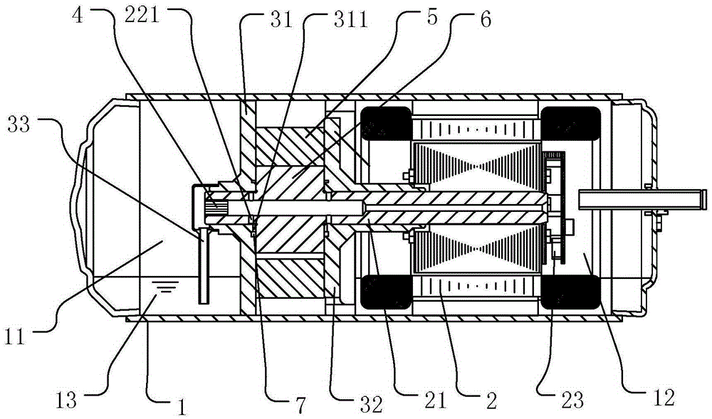
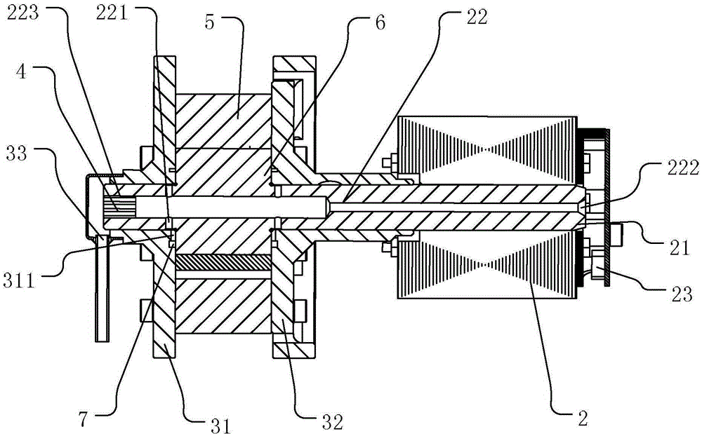
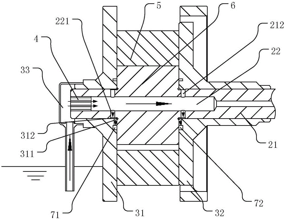
[0043] The directions in this application are defined as follows: the head end 81 of the slide plate 8 is the end away from the axis of the main shaft 21 , and the tail end 82 of the slide plate 8 is the end close to the axis of the main shaft 21 . The tail cavity 610 of the slide groove 61 is a part close to the axis of the main shaft 21 .

[0044] Such as Figure 1-9 As shown, the present invention relates to a vane compressor, the structure of which is mainly composed of a h...


PUM


Abstract

The invention aims at providing a slide vane compressor. The problem that backpressure oil supplying of an existing slide vane compressor is not stable is mainly solved. According to the technical scheme, negative pressure is generated in a main oil way in a spindle through a fan, and then an upper oil tube assembly is used for pumping oil from an oil pool; a backpressure oil tank is communicated with the main oil way, and the main oil way supplies pressure oil to the backpressure oil tank. Through the arrangement, oil supplying of the backpressure oil tank is more stable and reliable.

Description

technical field [0001] The invention relates to the field of compressors, in particular to a sliding vane compressor. Background technique [0002] The back pressure of the traditional vane compressor is supplied by the back pressure oil channel on the lower bearing, and the power is provided by the pressure difference between the oil pool and the tail of the vane slot. The followability is not good, resulting in leakage of the front and rear chambers of the slide. [0003] Specifically, such as Figure 10-12 The vane compressor shown in is mainly composed of a housing 921, a main shaft 98, a cylinder 97, upper and lower bearings 961, 962, etc., and its back pressure oil is supplied from the oil pool 923 to the back pressure oil tank 95 through the back pressure oil channel 93 . The back pressure oil channel 93 is a radial blind hole opened on the lower bearing 961, such as figure 2 , which terminates in the back pressure oil groove 95 and communicates with the back pres...

Claims


Application Information

Patent Timeline
Patent Type & Authority Applications(China)
IPC IPC(8): F04C23/02F04C18/344F04C29/00
Inventor 罗发游万鹏凯吴飞
Owner ZHUHAI GREE REFRIGERATION TECH CENT OF ENERGY SAVING & ENVIRONMENTAL PROTECTION
Why Eureka
Try Eureka