Working medium filling system and working medium filling method

A technology of working medium and filling medium, which is applied in the direction of container filling method, container discharge method, pipeline system, etc., can solve the problems of working medium gas volume not meeting the design requirements, low saturated steam pressure, large error, etc., to achieve The effect of low non-condensable gas content, stable filling flow rate and reasonable structure setting

Pending Publication Date: 2022-05-27
北京微焓科技有限公司
View PDF0 Cites 0 Cited by
  • Summary
  • Abstract
  • Description
  • Claims
  • Application Information

AI Technical Summary

Problems solved by technology

[0003] Generally, the working fluid working in the 100-200K temperature range has a relatively low saturated vapor pressure at room temperature. In this case, if it is filled at room temperature, the amount of working fluid gas often cannot meet the design requirements.
The use of low-temperature filling requires constant control of the quality of the filling process, and repeated filling often leads to relatively large errors.

Method used


Image

  • Working medium filling system and working medium filling method
  • Working medium filling system and working medium filling method
  • Working medium filling system and working medium filling method

Examples


Embodiment 1

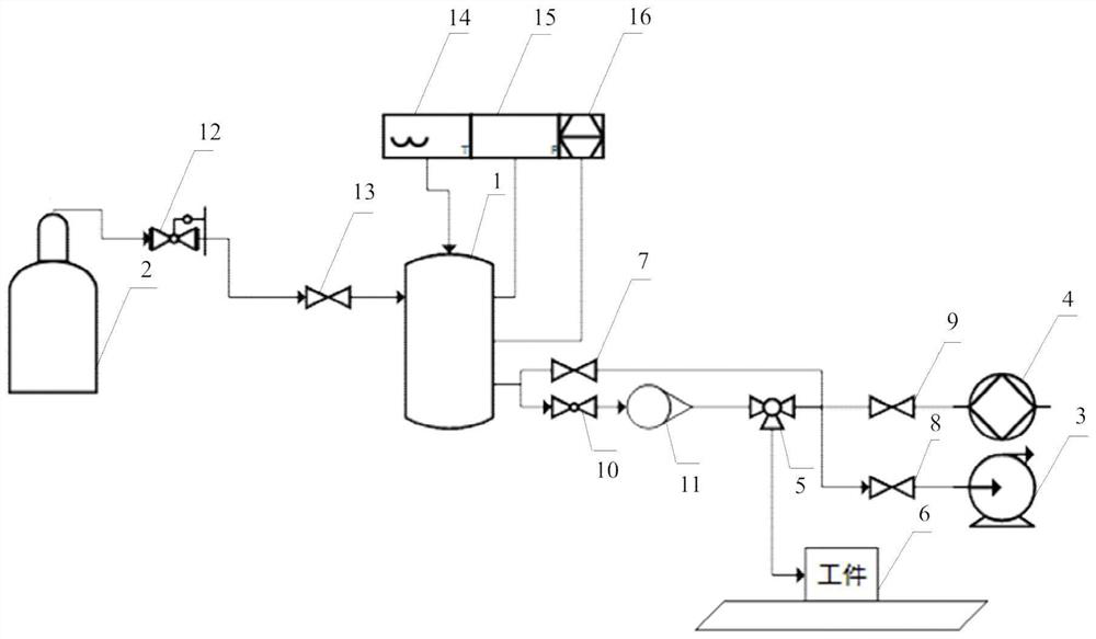
[0079] One working fluid filling system provided in the present embodiment is provided, such as Figure 1 Shown, comprising: a first working fluid storage device 1, a second working fluid storage device 2, a first vacuum device 3 and a second vacuum device 4;

[0080] Wherein, the first working fluid storage device 1 and the second working fluid storage device 2 are connected to each other; the first working fluid storage device 1 is connected to the first vacuum device 3 and the second vacuum device 4 are connected by the first and second lines, respectively; the second pipeline is further provided with a three-way commutation valve 5, the three-way commutation valve 5 for connecting the first working fluid storage device 1, the second vacuum device 4 and the workpiece to be charged working medium 6; the first line is connected to the second pipe, And communicate at the connection point;

[0081]On the first piping, the connection point and the first working fluid storage device 1...

Embodiment 2

[0085] The present embodiment provides a method of filling the working fluid, comprising the following steps:

[0086] 1, using the first vacuum device 3 to the first working fluid storage device 1 vacuum, the vacuum degree of the first working fluid storage device 1 ≤ 10Pa, close the first vacuum device 3, start the second vacuum device 4; the vacuum degree of the first working fluid storage device 1 ≤ 10 -2 Pa, close the second vacuum device 4; after closing the second vacuum device 4, to the first working fluid storage device 1 to fill the working medium; after filling the working fluid will be discharged from the first working fluid storage device 1;

[0087] 2, repeat step 1 5 times, control the temperature of the first working fluid storage device 1 is 259.9 ~ 260.1K;

[0088] 3, the second working fluid storage device 2 to the first working fluid storage device 1 after the first ventilation treatment is filled with working fluids;

[0089] 4, the use of the first vacuum dev...


PUM


Abstract

The invention relates to the field of working medium filling, in particular to a working medium filling system and a working medium filling method. The working medium filling system comprises a first working medium storage device, a second working medium storage device, a first vacuum device and a second vacuum device, wherein the first working medium storage device is connected with the second working medium storage device; the first working medium storage device is connected with the first vacuum device and the second vacuum device through a first pipeline and a second pipeline respectively; a three-way reversing valve is further arranged on the second pipeline and used for being connected with the first working medium storage device, the second vacuum device and a workpiece to be filled with the working medium; the first pipeline is connected with the second pipeline, and the first pipeline and the second pipeline are communicated with each other at a connecting point. The working medium filling system is reasonable in arrangement, high in safety and capable of achieving accurate filling of the working medium.

Description

Technical field [0001] The present invention relates to the field of working fluid filling, in particular, to a working fluid filling system and a method of working fluid filling. Background [0002] There are two common methods for filling the working fluid of the loop heat pipe: normal temperature filling and low temperature filling. Normal temperature filling is suitable for normal temperature loop heat pipes and low temperature loop heat pipes with high working fluid saturation pressure at room temperature. The low temperature filling is mainly used for low temperature loop heat pipe, it is by cooling the working medium gas that has entered the tube body, while refilling the new working medium gas, until the filling of the working mass to meet the pre-calculated requirements, low temperature filling often needs to repeatedly fill the heat pipe into the working fluid. [0003] Generally working in the 100-200K temperature zone of the working medium, its saturated vapor pressur...

Claims


Application Information

Patent Timeline
Patent Type & Authority Applications(China)
IPC IPC(8): F17C5/06F17C13/02F17C13/04F17D1/04F17D1/065F17D3/01
CPCF17C5/06F17C13/02F17C13/026F17C13/04F17D1/04F17D1/065F17D3/01F17C2221/01F17C2223/0123F17C2223/035F17C2227/0135F17C2227/045F17C2250/032F17C2250/0439F17C2260/02
Inventor 连红奎张晓屿尹航刘新生张晓林冉方圆孙萌
Owner 北京微焓科技有限公司
Why Eureka
Try Eureka