Method for friction-deformation-diffusion welding of circular-groove-assisted reinforcing tube plate
A technology of diffusion welding and annular groove, applied in welding equipment, non-electric welding equipment, metal processing equipment, etc., can solve problems such as complex production process, high-temperature joint relaxation, gap corrosion, etc., to reduce production costs, avoid cracks, and improve sealing sexual effect
- Summary
- Abstract
- Description
- Claims
- Application Information
AI Technical Summary
Problems solved by technology
Method used
Image
Examples
specific Embodiment approach 1
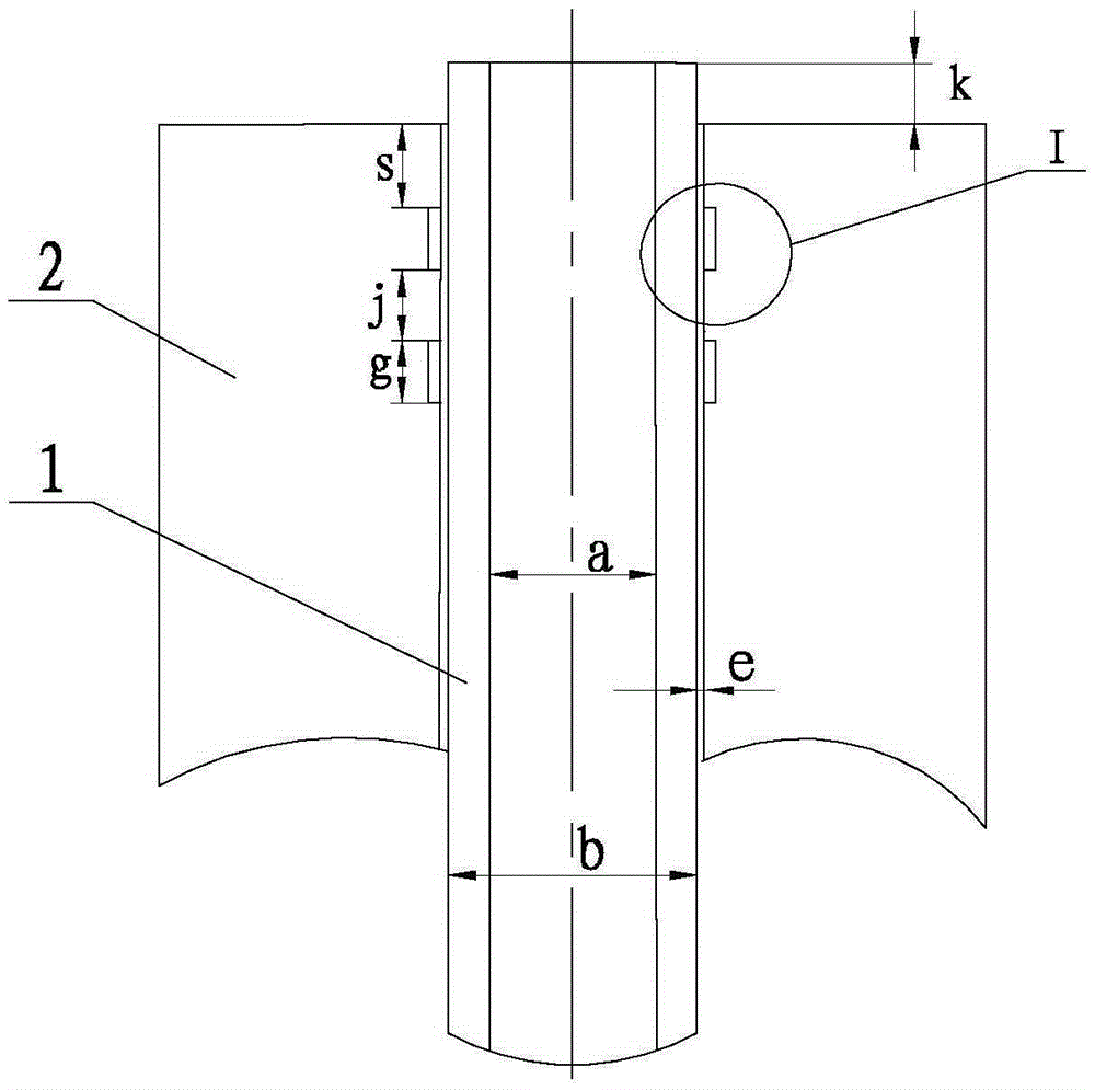
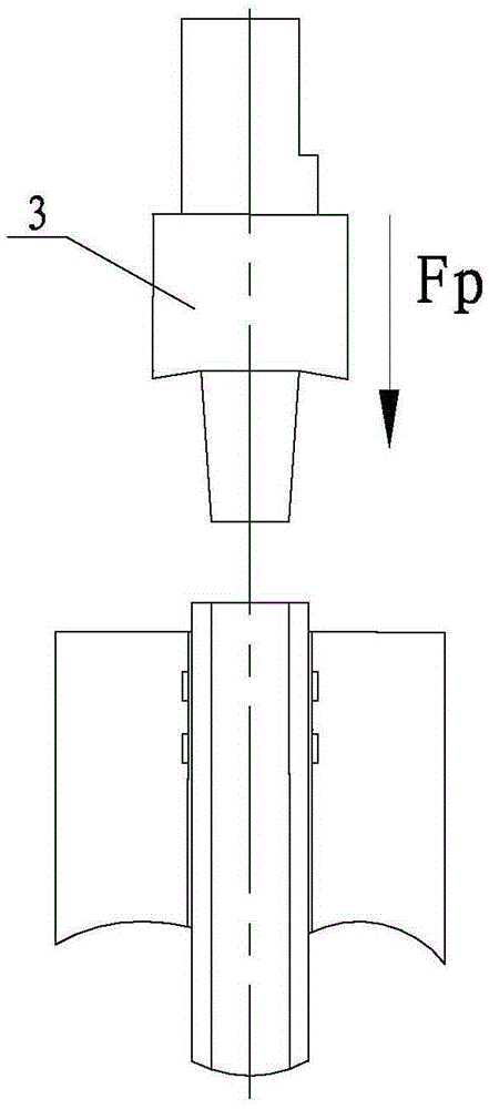
[0027] Specific implementation mode one: combine Figure 1 to Figure 8 Describe this implementation mode, this implementation mode is realized through the following steps:
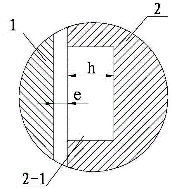
[0028] Step 1. Annular grooves 2-1 are formed on the inner wall of the tube sheet 2: before welding, 1 to 3 annular grooves 2-1 are formed at a distance s from the upper surface of the tube sheet 2 to assist in strengthening the connection strength of the tube-plate structure, see figure 1 and figure 2 ;
[0029] Step 2, pre-welding treatment: first remove the oxide film on the inner and outer walls of the tube 1, the upper surface of the tube sheet 2, and the surface of the annular groove 2-1 by mechanical grinding, and then use an organic solvent or cleaning agent to wipe the surface of the tube 1 and the tube sheet 2, Remove oil and metal dust;
[0030] Step 3, clamping of tube 1 and tube plate 2: when clamping, the gap between the outer wall of tube 1 and the inner hole of tube plate 2 is e, and t...
specific Embodiment approach 2
[0033] Specific implementation mode two: combination figure 1 and figure 2 To describe this embodiment, in this embodiment, in step 1, the width g of the annular groove 2 - 1 is 2 mm to 5 mm, and the depth h is 0.1 mm to 0.5 mm. Other steps are the same as in the first embodiment.
specific Embodiment approach 3
[0034] Specific implementation mode three: combination figure 1 Describe this embodiment. In this embodiment, in step 1, the distance from the annular groove 2-1 to the upper surface s of the tube plate is 3 mm to 10 mm, and the groove distance j between two adjacent annular grooves 2-1 is 2 mm to 8 mm. Other steps are the same as those in Embodiment 1 or 2.
PUM
| Property | Measurement | Unit |
|---|---|---|
| width | aaaaa | aaaaa |
| depth | aaaaa | aaaaa |
| length | aaaaa | aaaaa |
Abstract
Description
Claims
Application Information
 - R&D
- Intellectual Property
- Life Sciences
- Materials
- Tech Scout
- Unparalleled Data Quality
- Higher Quality Content
- 60% Fewer Hallucinations
Browse by: Latest US Patents, China's latest patents, Technical Efficacy Thesaurus, Application Domain, Technology Topic, Popular Technical Reports.
© 2025 PatSnap. All rights reserved.Legal|Privacy policy|Modern Slavery Act Transparency Statement|Sitemap|About US| Contact US: help@patsnap.com


