
Pile plate plane and vertical face intersecting combination auxiliary energy dissipater

An energy-dissipating and energy-dissipating technology, applied to underflow energy-dissipation. , In the field of three-dimensional underflow energy dissipation, it can solve problems such as increasing engineering costs, and achieve the effect of improving energy dissipation rate, obvious energy dissipation effect and stable structure.

Inactive Publication Date: 2016-03-23
WUHAN UNIV
View PDF4 Cites 4 Cited by
  • Summary
  • Abstract
  • Description
  • Claims
  • Application Information

AI Technical Summary

Problems solved by technology

When the energy dissipation rate is required to be high, multiple auxiliary energy dissipators such as toe piers, energy dissipation piers, and tail sills need to be used in combination, and the improvement of the energy dissipation rate is only improved, but the impact on the total resistance of water flow is small. Engineering costs have increased significantly

Method used


Image

  • Pile plate plane and vertical face intersecting combination auxiliary energy dissipater
  • Pile plate plane and vertical face intersecting combination auxiliary energy dissipater
  • Pile plate plane and vertical face intersecting combination auxiliary energy dissipater

Examples


Embodiment Construction

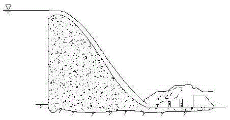
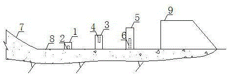
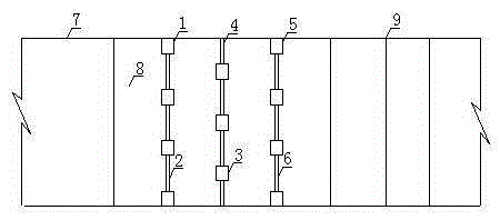
[0019] In order to facilitate those of ordinary skill in the art to understand and implement the present invention, the present invention will be described in further detail below in conjunction with the accompanying drawings and embodiments. It should be understood that the implementation examples described here are only used to illustrate and explain the present invention, and are not intended to limit this invention.

[0020] please see figure 1 , figure 2 and image 3 , the invention provides an auxiliary energy dissipator for the staggered combination of pile-slab planes and elevations. Three-level sheet pile structures are equidistantly arranged in the stilling pool 8 downstream of the discharge weir 7 to form a sheet pile dislocation with staggered spatial structures. Arrangement, so that the water flow appears rolling, to achieve the effect of multi-level auxiliary energy dissipation; the three-level sheet pile structure is composed of the first-level sheet pile str...


PUM


Abstract

The invention discloses a pile plate plane and vertical face intersecting combination auxiliary energy dissipater. Three levels of pile plate structures are arranged in an absorption basin at the downstream part of a discharging weir at equal distances to form space structure intersected pile plate displacement arrangement; rotary rolling exists in the water flow, and the multi-level auxiliary energy dissipating effect is achieved; and the pile plate structures are composed of a plurality of energy dissipating piles and high-low plates erected among the energy dissipating piles and are arranged on the same water passing section. When the water flow seriously impacts the pile plate structures, most energy is removed through the hydraulic jump, local resistance of piles enables the surrounding water of the piles to be subjected to shear friction, and part of energy is also dissipated; and through the energy dissipating piles arranged in a multi-level equal-height-difference manner, the flow speed gradient in the water flow can be increased, and the pattern of the hydraulic jump is changed; rotary rolling appears in the water flow in the absorption basin, so that the forced hydraulic jump is generated, and the aims of improving the energy dissipating rate and shortening the length of the absorption basin are achieved; and compared with a single plane arrangement auxiliary energy dissipater like an energy dissipating pier, the solid arrangement energy dissipater is more stable in structure and better in energy dissipating effect.

Description

technical field [0001] The invention belongs to the technical field of water conservancy and hydropower engineering, and relates to a three-dimensional underflow energy dissipator, in particular to a plum blossom pile-high and low plate type three-dimensional underflow energy dissipator, which is applied to the underflow energy dissipation downstream of drainage structures. Background technique [0002] In water conservancy and hydropower projects, the construction of hydraulic structures creates a water level difference between the upstream and downstream, resulting in a large potential energy difference. Most of the potential energy will inevitably be converted into kinetic energy when vented to the downstream, causing scour to the river bed and bank, destroying the foundation, and threatening Considering the safety of the drainage structure itself, engineering measures need to be taken to control the downstream water flow connection and energy dissipation. [0003] The ...

Claims


Application Information

Patent Timeline
Patent Type & Authority Applications(China)
IPC IPC(8): E02B8/06
CPCE02B8/06
Inventor 胡志根卢政佐魏鹏帅苏杨杨耿祺刘文
Owner WUHAN UNIV
Learn More