Gas drainage pipeline environment simulation device

An environmental simulation device and gas drainage technology, applied in gas discharge, safety devices, mining equipment, etc., can solve the problem of high risk, inability to simulate the gas drainage pipeline environment, and inability to analyze the flow of gas and cinder in detail, etc. problem, to achieve the effect of optimizing the design scheme

Active Publication Date: 2016-03-23
NORTH CHINA INST OF SCI & TECH
View PDF5 Cites 0 Cited by
  • Summary
  • Abstract
  • Description
  • Claims
  • Application Information

AI Technical Summary

Problems solved by technology

At present, due to the complex situation and high degree of danger in coal mines, it is impossible to analyze the flow of gas, water and cinder in the drainage pipe network in detail
[0003] Moreover, the actual working environment of the gas drainage pipeline also makes it difficult to carry out relevant research on the factors affecting the extraction efficiency in the drainage pipeline network in the underground environment: the coal mine gas drainage pipeline is installed and distributed in the coal mine roadway, and the length is determined by It depends on the actual situation; gas drainage is achieved by vacuum pumping, the air environment inside the entire pipeline is negative pressure, the negative pressure can reach -0.09MPa at the highest, and during the drainage process, the liquid water and coal slime in the coal rock formation are inevitable It flows into the discharge pipeline by its own weight and negative pressure; due to the temperature difference effect, the gaseous water in the pipeline will also condense into liquid water
[0004] In addition, the gas drainage pipeline environment cannot be simulated by simple equipment under normal laboratory conditions
Therefore, currently there is basically no device capable of simulating the internal environment of the underground gas drainage network in coal mines.

Method used


Image

  • Gas drainage pipeline environment simulation device
  • Gas drainage pipeline environment simulation device

Examples


Embodiment Construction

[0018] The present invention will be described in detail below in conjunction with the accompanying drawings and embodiments.

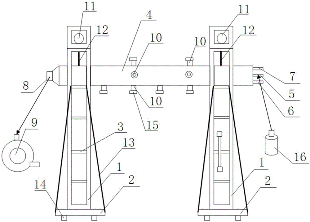
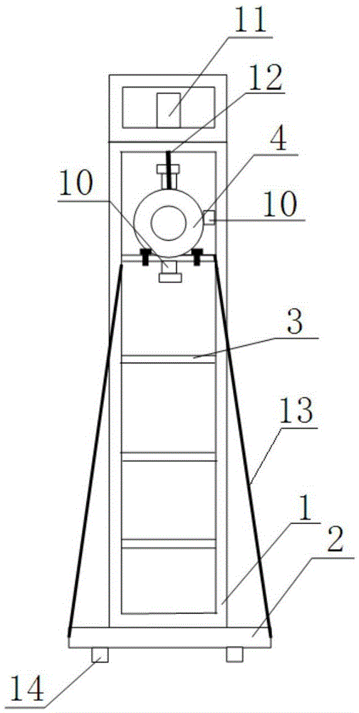
[0019] like figure 1 , figure 2 As shown, the present invention includes two vertical beams 1 arranged at intervals, and a base 2 is fastened to the lower end of each vertical beam 1 . A plurality of pairs of rams 3 are arranged at intervals up and down on the two vertical beams 1 , and each ram 3 is slidably connected in a vertical chute on the vertical beam 1 . A plurality of bolt holes are uniformly arranged up and down on each vertical beam 1 , and the ram 3 stops at the predetermined height of the vertical beam 1 through a bolt hole passing through the vertical beam 1 and its own bolt. In the present invention, one or more gas pipelines 4 can be set according to the experimental content, and the diameters of the gas pipelines 4 are different. Each gas pipeline 4 is supported on a pair of rams 3 at the same height. Both ends of the gas pipeli...


PUM


Abstract

The invention relates to a gas drainage pipeline environment simulation device. The gas drainage pipeline environment simulation device comprises two vertical beams oppositely arranged in a spaced mode. One or more horizontally-arranged gas pipelines are arranged between the two vertical beams. The gas pipelines are detachably connected with the vertical beams. The two ends of each gas pipeline are closed. Three branch pipes are connected to one closed end of each gas pipeline, and an exhaust branch pipe is arranged at the other closed end of each gas pipeline. Each exhaust branch pipe is connected with a vacuum pump. A plurality of branch pipes connected with an instrument are arranged on the side walls of the gas pipelines. The gas drainage pipeline environment simulation device can be used for simulating the working environment of the gas pipelines in a laboratory, the pressure change rule inside the gas exhaust pipes and gas, coal dust and water mixture characteristic change rules and the like are researched by precise measurement of a measuring instrument, and therefore the correlational research of the gas pipelines can be achieved on the safety condition.

Description

technical field [0001] The invention relates to a simulation device, in particular to a gas drainage pipeline environment simulation device. Background technique [0002] Coal mine gas extraction refers to the use of gas pumps or other drainage equipment to extract high volume fraction of gas in the coal seam, and then discharge the extracted high volume fraction gas to the ground or the mine's total return airway through a pipe network isolated from the roadway. Coal mine gas drainage is a fundamental measure to control coal mine gas, and gas leakage, water blockage and slag blockage in gas drainage pipelines are the main factors affecting the efficiency of gas drainage. At present, due to the complex situation and high degree of danger in coal mines, it is impossible to analyze the flow of gas, water and cinder in the drainage pipe network in detail. [0003] Moreover, the actual working environment of the gas drainage pipeline also makes it difficult to carry out relevan...

Claims


Application Information

Patent Timeline
IPC IPC(8): E21F7/00
CPCE21F7/00
Inventor 陈学习李东明
Owner NORTH CHINA INST OF SCI & TECH
Why Eureka
Try Eureka