Low-temperature explosion-proof turbocharger

A turbocharger, explosion-proof technology, applied in the direction of machines/engines, engine components, mechanical equipment, etc., to increase the driving force and reduce the working temperature

Inactive Publication Date: 2016-03-23
CHANGZHOU PINGJIANG ELECTRICAL EQUIP CO LTD
View PDF0 Cites 1 Cited by
  • Summary
  • Abstract
  • Description
  • Claims
  • Application Information

AI Technical Summary

Problems solved by technology

[0003] The generator set used in the mine exploration and mining process must be explosion-proof, the engine is the core equipment in the generator set, and the turbocharger is a key component of the engine, and the turbocharger operates at a high temperature. Its exhaust temperature is above 300 degrees. According to the explosion-proof technical requirements of coal mines and rock gas mining, the exhaust temperature of the engine should be lower than 70 degrees. This puts forward very high requirements for the working temperature of the turbocharger. The existing None of the turbochargers can meet the requirements

Method used


Image

  • Low-temperature explosion-proof turbocharger
  • Low-temperature explosion-proof turbocharger
  • Low-temperature explosion-proof turbocharger

Examples


Embodiment 1

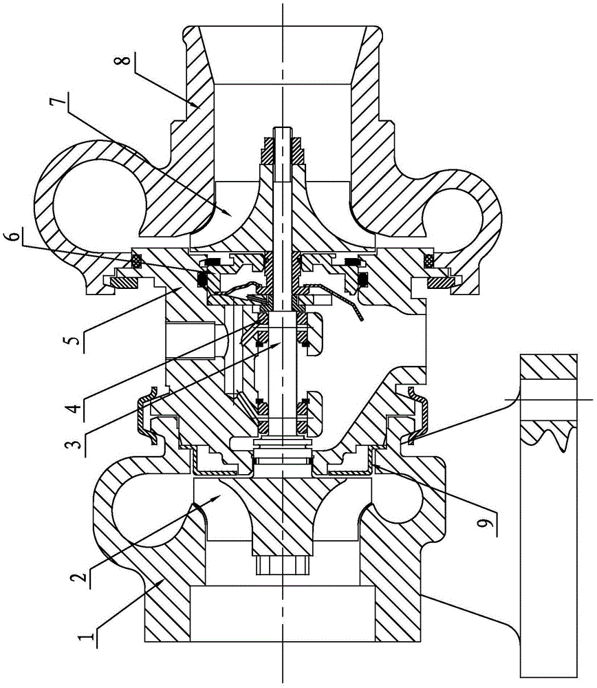
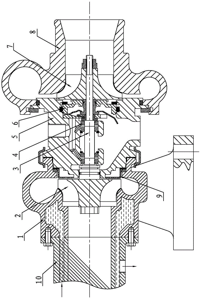
[0025] A low-temperature explosion-proof turbocharger, including a turbine casing 1, a turbine 2, a turbine shaft 3, a sliding bearing 4, an intermediate body 5, a diffuser plate 6, a booster impeller 7, a pressure casing 8, a bridge break heat insulation structure 9 and The water-cooled exhaust temperature control pipe 10, the turbine 2 and the booster impeller 7 are respectively installed at both ends of the turbine shaft 3, the turbine 2 is located in the turbine housing 1, the booster impeller 7 is located in the pressure housing 8, and the turbine shaft 3 is passed through two sliding The bearing 4 is installed on the intermediate body 5, the turbine casing 1 is fixedly installed on the left side of the intermediate body 5 through the broken bridge heat insulation structure 9, the pressure shell 8 is fixedly installed on the right side of the intermediate body 5 through the diffuser plate 6, and the intermediate body 5 The lubricating oil passage is connected with the two ...

Embodiment 2

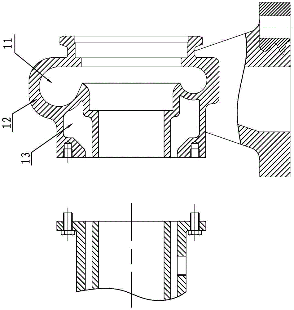
[0026] Embodiment 2: The difference from Embodiment 1 lies in the shape of the inner surface of the cooling water passage 13. In this example, the radial cross-section shape of the cooling water passage 13 in the turbine shell 1 is wave-shaped, which can not only further increase the water and The contact area of ​​the turbine shell can also reduce the residence time of water in the cooling water channel 13, and the cooling effect on the turbine shell is better.


PUM


Abstract

The invention discloses a low-temperature explosion-proof turbocharger. The low-temperature explosion-proof turbocharger comprises a turbine shell, a middle body, a press shell, a broken-bridge heat isolation structure and a water-cooling exhaust temperature-control tube, wherein a cooling water channel is arranged in the outer sidewall of a vortex gas channel of the turbine shell; the cooling water channel is connected with a pressure water source; a water outlet of the cooling water channel is connected with a cooling water pool; the broken-bridge heat isolation structure is arranged between the turbine shell and the middle body; and the water-cooling exhaust temperature-control tube is in sealing connection with an exhaust port of the turbine shell. According to the invention, through the three measures of carrying out water cooling on the turbine shell, arranging the broken-bridge heat isolation structure for realizing heat isolation between the turbine shell and the middle body, and abutting the water-cooling exhaust temperature-control tube at the exhaust port of the turbine shell, the temperature of an exhaust gas can be effectively controlled only by controlling the flow rate and the flow speed of cooling water entering the water-cooling exhaust temperature-control tube; and in this way, the working temperatures of the turbine shell, the middle body and the press shell can be effectively controlled, and the temperature of the final exhaust gas of the turbine shell can also be reduced and controlled, so that the working temperature of the turbocharger is reduced to be below a pre-control temperature, and the explosion-proof performance of the turbocharger is guaranteed.

Description

【Technical field】 [0001] The invention relates to an exhaust turbocharger, in particular to an explosion-proof turbocharger suitable for mine mining sites. 【Background technique】 [0002] The exhaust-type turbocharger uses the pressure and high-temperature exhaust gas discharged from the engine as a power source. The high-temperature and pressure exhaust gas discharged from the engine is introduced into the turbine in the turbocharger, and the energy contained in the exhaust gas is used to drive the turbine in the turbine to rotate, thereby driving the turbine. At the same time, it drives the coaxial compressor impeller to rotate, and the compressor compresses the inhaled air and sends it to the intake system of the engine, and fills the engine cylinder with high-density air to increase the oxygen content in the cylinder. It can increase the output power of the same type of engine, and can also significantly improve the economy of the engine, promote the full combustion of d...

Claims


Application Information

Patent Timeline
IPC IPC(8): F01D25/08F01D25/14
CPCF01D25/08F01D25/14F05D2220/40
Inventor 周惠娟
Owner CHANGZHOU PINGJIANG ELECTRICAL EQUIP CO LTD
Why Eureka
Try Eureka