Vibronic Sensor

A vibration unit and mechanical vibration technology, applied in the direction of instruments, scientific instruments, engine components, etc., can solve complex problems, achieve the effect of reducing power consumption and simplifying calculation work

Active Publication Date: 2016-03-23
EHNDRESS KHAUZER GMBKH KO KG
View PDF8 Cites 6 Cited by
  • Summary
  • Abstract
  • Description
  • Claims
  • Application Information

AI Technical Summary

Problems solved by technology

However, in practice this is relatively complex

Method used


Image

  • Vibronic Sensor
  • Vibronic Sensor
  • Vibronic Sensor

Examples


Embodiment Construction

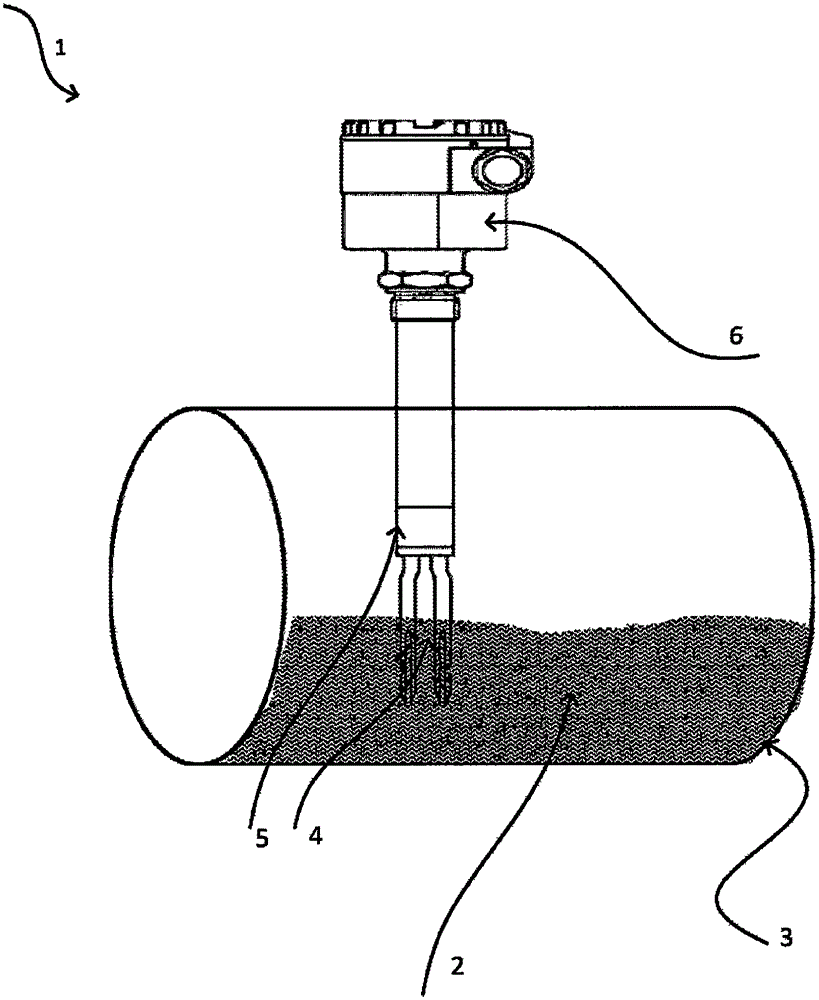
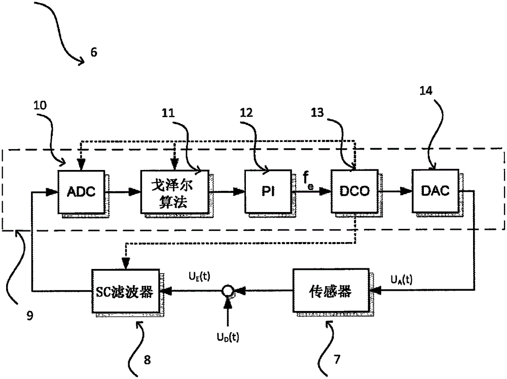
[0063] Electronic vibration sensor 1 in figure 1 shown in . The vibratable unit 4 is represented in the form of an oscillating tuning fork, which is partially immersed in the medium 2 located in the container 3 . The vibratable unit is excited by the electromechanical transducer unit 5 to vibrate mechanically, for example, it may be a piezoelectric stack actuator or a coupling actuator. However, it is naturally understood that other embodiments of the electronic vibration sensor also fall within the protection scope of the present invention. Furthermore, the electronics unit 6 is represented by means by which signal evaluation and / or signal feedback can take place. The essential device block diagram of the electronic unit according to the present invention is figure 2 Theme of.

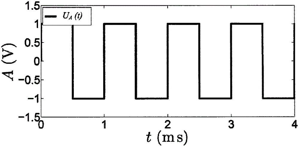
[0064] sensor element 7, consisting of figure 1 The vibratable unit 4 and the electromechanical transducer unit 5 are provided with an excitation signal U A . Conversely, from the mechanical...


PUM


Abstract

A method to determine and / or monitor at least one process variable of a medium with at least one vibration-capable unit. The vibration-capable unit is excited to mechanical vibrations by means of an electrical excitation signal of an adjustable frequency; wherein the mechanical vibrations are transduced into a received electrical signal, which is characterized at least by a frequency and / or a phase and / or an amplitude. The excitation signal is generated based on the received signal; wherein the voltage values of the received signal are sampled at specified predetermined points in time, starting from the excitation signal. The real part and the imaginary part of the received signal are determined from the sampled voltage values of the received signal by means of a Goertzel algorithm; wherein at least one Goertzel coefficient-in particular the number of the sample values and / or an operating frequency and / or a sample frequency-is provided for performing the Goertzel algorithm. At least the current phase and / or the current amplitude of the received signal are calculated from the real part and the imaginary part of the received signal; wherein the frequency of the excitation signal is adjusted such that a predeterminable phase shift is present between the excitation signal and the received signal; and wherein the at least one process variable is determined.

Description

technical field [0001] The invention relates to a method and a device for monitoring at least one process variable of a medium having at least one vibratory unit. Background technique [0002] For example, in the case of liquid level measuring devices, such devices - likewise designed as electronic vibration sensors - have, for example, an oscillating tuning fork, a separate rod or a diaphragm as the vibrating element. During operation, such a vibratable unit is excited into mechanical vibration by an electromechanical transducer unit, for example excited in turn by a piezoelectric actuator or an electromagnetic actuator. In the case of a flow rate measuring device, however, the vibratable unit can also be designed as a vibratable pipe through which the corresponding medium flows, for example in a measuring device operating according to the Coriolis principle. It is naturally understood that other possibilities likewise within the scope of the invention also arise in vibrat...

Claims


Application Information

Patent Timeline
Patent Type & Authority Applications(China)
IPC IPC(8): G01F23/296G01N9/00G01F1/66
CPCG01F1/666G01F23/2966G01N9/00G01F23/2967G01N9/002G01N2009/006G01F23/802G01F1/66G01F23/284G01F1/20G01F23/296G01H11/06
Inventor 托比亚斯·布伦加藤纳卢卡斯·格斯巴赫
Owner EHNDRESS KHAUZER GMBKH KO KG
Why Eureka
Try Eureka