An in-situ test device and method for the sedimentation and deposition process of water particles

An in-situ test and deposition process technology, applied to the analysis of materials, instruments, etc., can solve the problems of destroying the layered deposition characteristics of particles, short capture time, and inability to reflect the environmental information of particle layers, and achieve simple structure and operability Good performance and easy processing

Active Publication Date: 2018-04-17
CHONGQING INST OF GREEN & INTELLIGENT TECH CHINESE ACADEMY OF SCI
View PDF9 Cites 0 Cited by
  • Summary
  • Abstract
  • Description
  • Claims
  • Application Information

AI Technical Summary

Problems solved by technology

Because the capture time is too short, it can only reflect the particle information of the sedimentation in a specific period, and cannot reflect the layered environmental information of the sedimentation process in different periods (such as different seasons).
[0008] 3) If the time is extended (half a year or a year) or the content of sedimentation particles is relatively large, although specific and actual sedimentary layer characteristics can be formed in the sedimentation tank, the current treatment of the captured sediment is usually to mix and filter the water to develop the material Therefore, the layered deposition characteristics of particulate matter in different periods were significantly destroyed.
This is of great significance for mastering the morphological changes and biogeochemical processes of particulate matter sedimentation and deposition, but the current settling tank and its in-situ test design have not been able to realize the observation of the above processes

Method used


Image

  • An in-situ test device and method for the sedimentation and deposition process of water particles
  • An in-situ test device and method for the sedimentation and deposition process of water particles
  • An in-situ test device and method for the sedimentation and deposition process of water particles

Examples


Embodiment

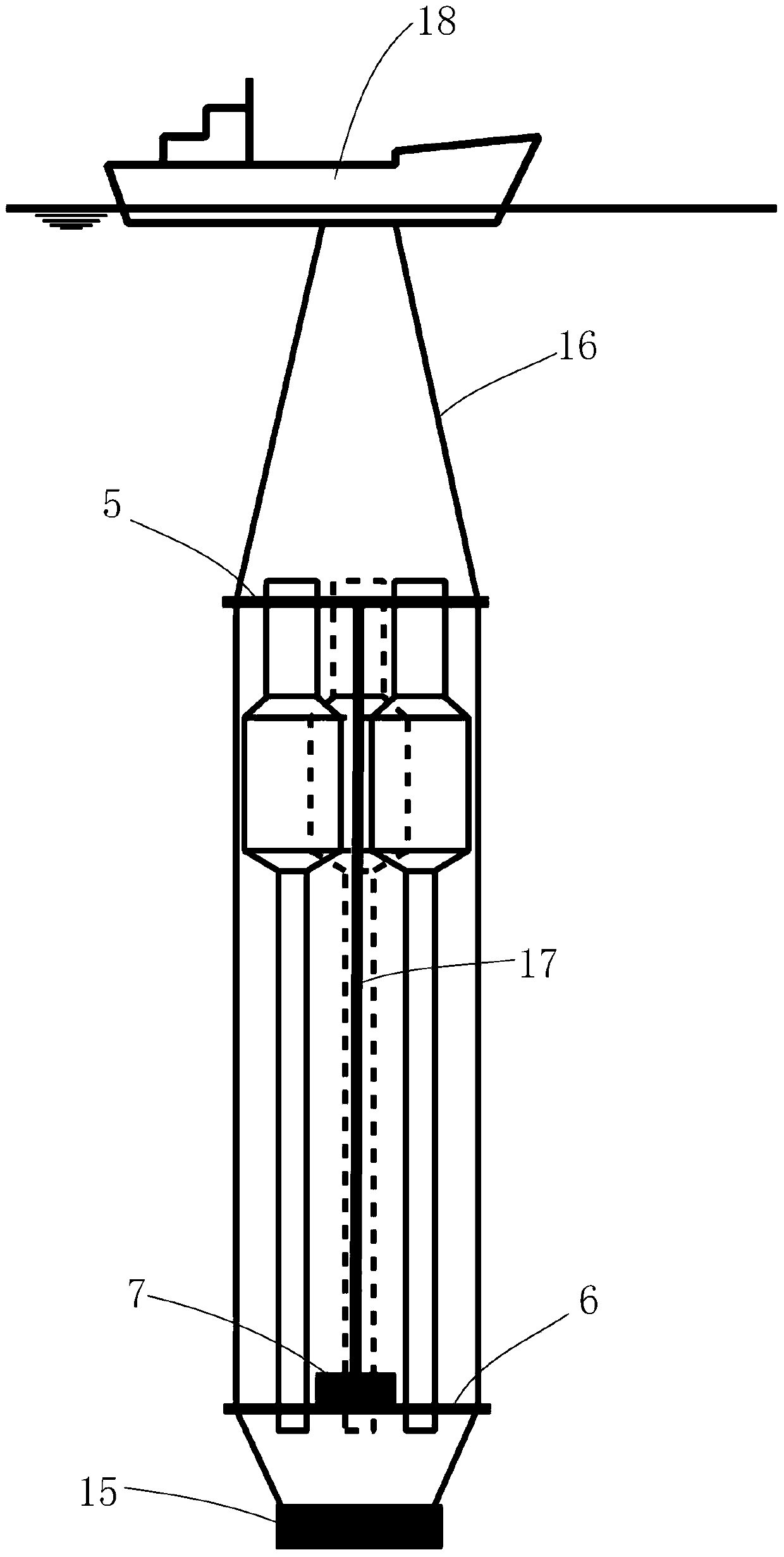
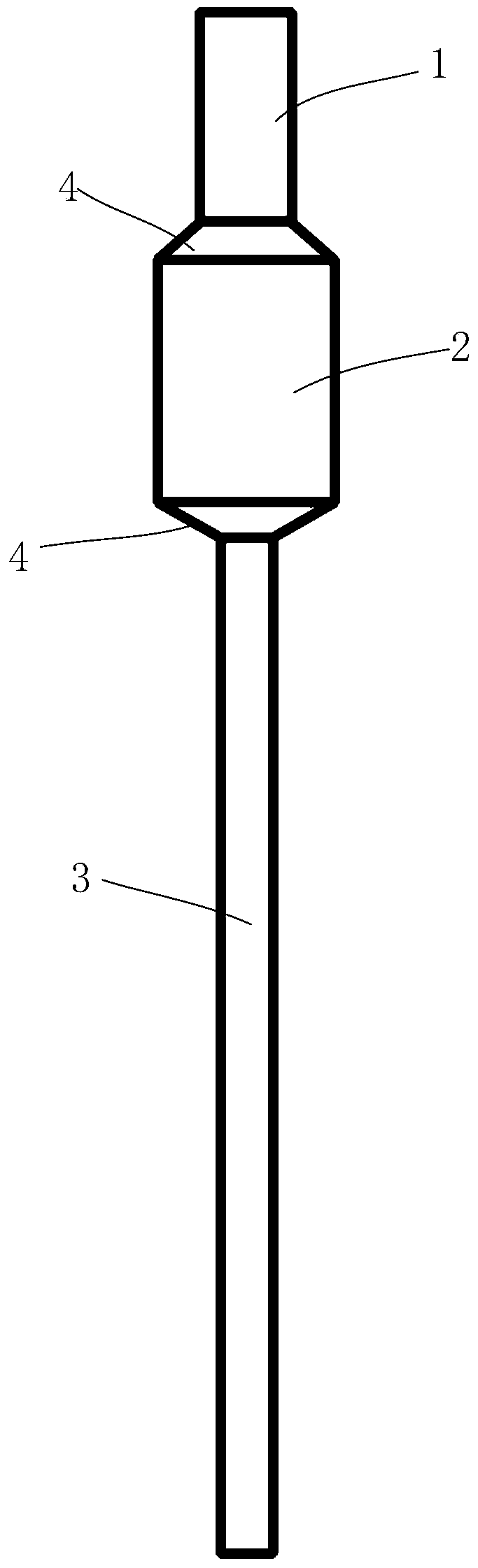
[0080] According to the above-mentioned invention, an in-situ test observation is carried out in a water area in the Three Gorges Reservoir area of ​​the Yangtze River by using a set of in-situ test devices. Among them, the three sets of dustfall traps are all 2.0m in height, integrated and fixed on the support mechanism to form a complete set of dustfall traps. Among them, the diameter of the entrance zone 1 is 0.15m, and the height is 0.2m; the diameter of the settlement zone 2 is 0.3m, and the height is 0.3m; the diameter of the sedimentation zone is 0.1m, and the height is 1.5m.

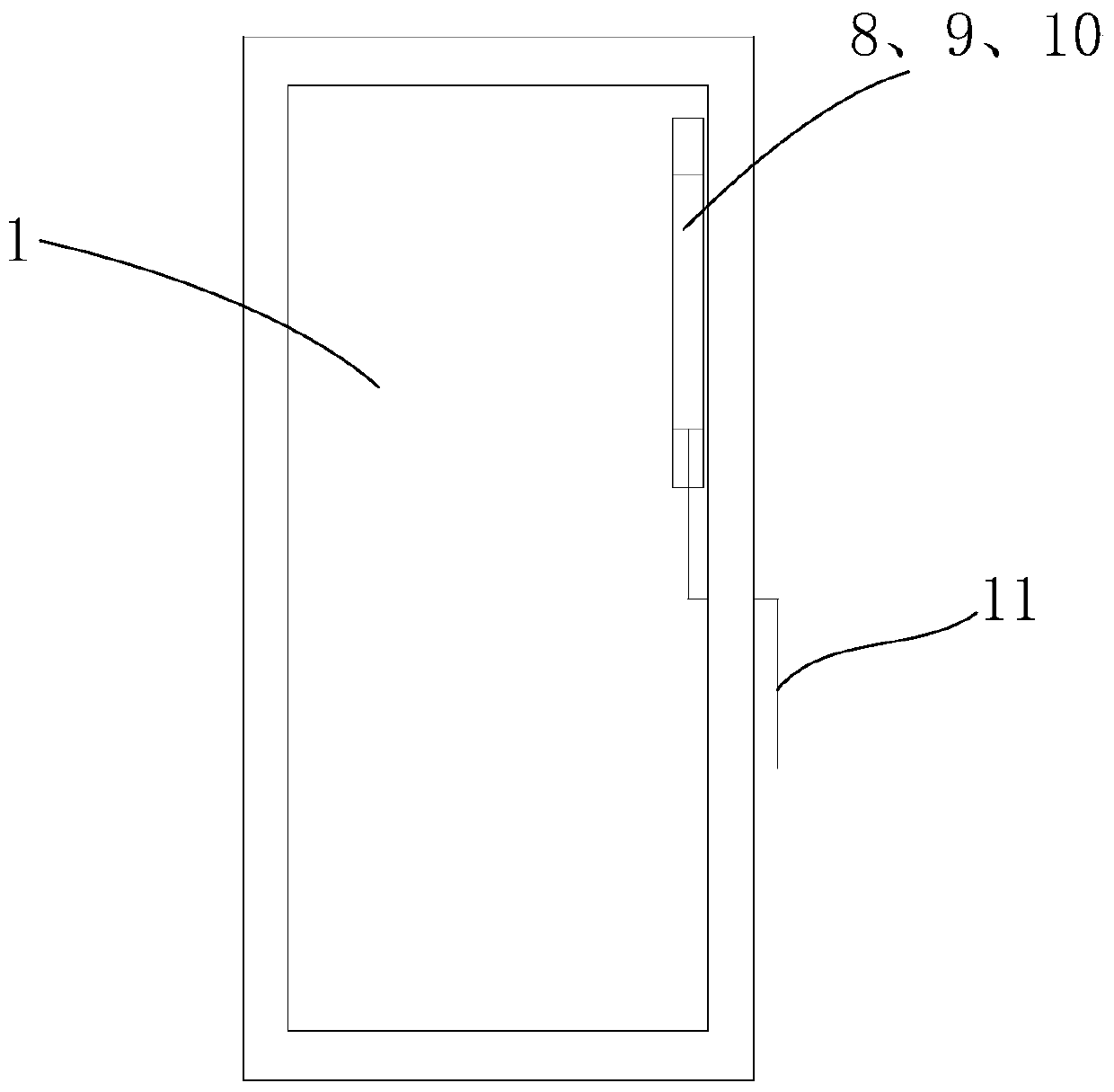
[0081] There are two real-time monitoring probes for water temperature and dissolved oxygen in the inlet section and the sedimentation section of the sedimentation particle trap, and one set of probes in the sedimentation area is located at the bottom of the device. The data collection frequency is once every 24 hours, and the release time of the device is 3 months (June to August), a total of 90...


PUM

PropertyMeasurementUnit
diameteraaaaaaaaaa

Abstract

The invention provides an in-situ test device and method for the settling and precipitating process of aquatic particles. The device comprises a supporting mechanism and a settling particle catcher installed on the supporting mechanism. The settling particle catcher is of a barrel-shaped structure with the open upper end and the closed lower end. The settling particle catcher comprises an inlet region, a settling region and a precipitating region which are formed from top to bottom. Multiple sampling holes with different heights are formed in the side wall of the precipitating region. Multiple monitoring probes are arranged in the inlet region and the precipitating region. Long-term following observation and real-time information acquisition of the precipitating process of the aquatic particles can be achieved, it is guaranteed that the settling and precipitating process is stable, interference of disturbance of external water power or other factors with the precipitating process can be avoided, and the situation that the caught settling particles are suspended again due to other conditions is avoided. Precipitating and layering effects of the particles in different periods can be formed, and the particles in different precipitating layers in the settling particle catcher can be obtained on the premise that the precipitating and layering structure is not damaged.

Description

technical field [0001] The invention belongs to the field of ecological environment, and specifically relates to an in-situ test device and method for the sedimentation and deposition process of water particles, which are applied to field sampling and in-situ test research of environmental geochemistry and biogeochemistry of water bodies such as reservoirs, lakes, and oceans . Background technique [0002] The particulate matter in the water body mainly comes from the particulate matter produced by the water body itself (plankton and its excrement and debris), the deposition of atmospheric particulate matter, the input of terrestrial and upstream particulate matter, and the resuspension of sediments. [0003] In reservoirs, lakes, oceans and other water bodies, water particles will gradually settle under the action of gravity due to the slowing of the water flow velocity and deposit on the bottom of the reservoir or the bottom of the lake. Over the years, the sediments with...

Claims


Application Information

Patent Timeline
Patent Type & Authority Patents(China)
IPC IPC(8): G01N15/04
CPCG01N15/04
Inventor 李哲鲁伦慧马健荣郭劲松肖艳
Owner CHONGQING INST OF GREEN & INTELLIGENT TECH CHINESE ACADEMY OF SCI
Why Eureka
Try Eureka