Resolution ratio performance measuring device of cone beam CT and calibration method

A technology of measuring device and calibration method, which is applied in the directions of measuring device, analyzing materials, and using radiation for material analysis, etc., can solve the problems of being easily affected by human factors, complex manufacturing process, and discrete, etc., and achieves low manufacturing cost and easy implementation. , the effect of simple structure

Active Publication Date: 2016-03-23
FOURTH MILITARY MEDICAL UNIVERSITY
View PDF6 Cites 8 Cited by
  • Summary
  • Abstract
  • Description
  • Claims
  • Application Information

AI Technical Summary

Problems solved by technology

This method is simple and direct, but has the following disadvantages: firstly, the method relies on the naked eye observation of the inspector, and is easily affected by human factors; secondly, the line pair interval is discrete, and the image cannot reflect the modulation degree of all spatial frequencies; in addition, the interval is small The production process of the wire pair is complicated, which cannot meet the measurement requirements of the high-resolution CT system
However, the current CT calibration method only considers the lateral resolution, and there is a lack of devices and methods specifically for cone-beam CT resolution measurement.

Method used


Image

  • Resolution ratio performance measuring device of cone beam CT and calibration method
  • Resolution ratio performance measuring device of cone beam CT and calibration method
  • Resolution ratio performance measuring device of cone beam CT and calibration method

Examples


Embodiment Construction

[0056] The present invention will be further described below in conjunction with the embodiments and with reference to the accompanying drawings.

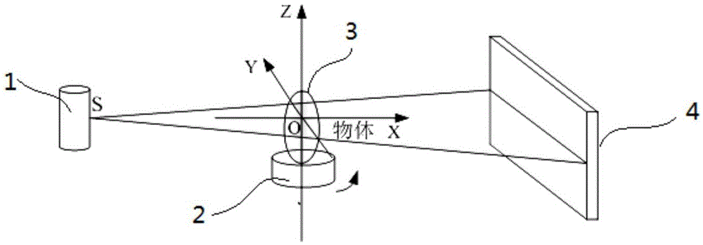
[0057] See figure 1 . figure 1 It embodies the coordinate system of the cone beam CT system, wherein the cone beam CT system mainly includes the main components such as the ray source 1, the rotating table 2, and the flat panel detector 4, and the plane SOZ formed by the focus S of the ray source and the rotation axis is perpendicular to the plane of the detector 4, and The projection of the focal point on the detector 4 is located at the center of the detector 4 . The object is placed on the turntable 2, and the turntable 2 rotates around the Z axis to realize the acquisition of cone beam CT projection data.

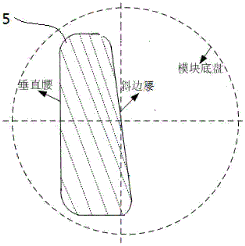
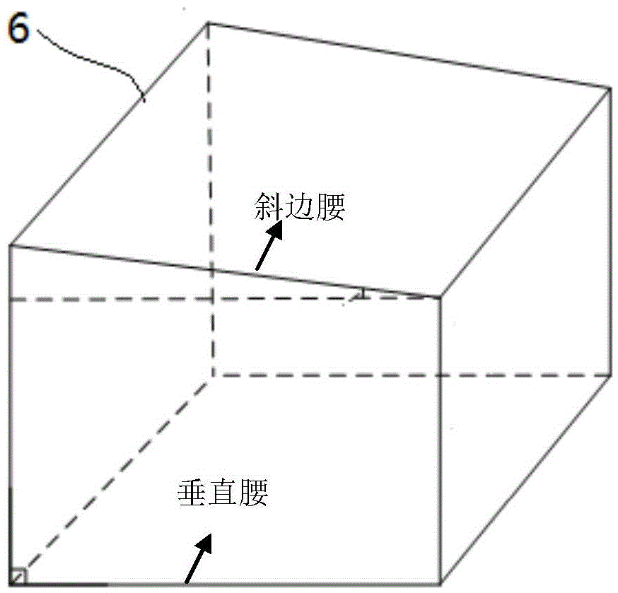
[0058] See figure 2 . Schematic diagram of the cross-section of the lateral resolution measurement module. The cross-section is trapezoidal, one of the waists of the trapezoid is perpendicular to the upper and lower bas...


PUM

PropertyMeasurementUnit
lengthaaaaaaaaaa
lengthaaaaaaaaaa
radiusaaaaaaaaaa

Abstract

The invention relates to a resolution ratio performance measuring device of a cone beam CT and a calibration method. The measuring device comprises a transverse resolution ratio measuring module and a longitudinal resolution ratio measuring module. By means of the device, the transverse resolution ratio and the longitudinal resolution ratio of the cone beam CT can be calibrated. The calibration method includes the steps of conducting collecting and three-dimensional reconstructing on the cone beam CT through the two modules of the measuring device, generating an edge expansion function on the central cross section of the transverse resolution ratio measuring module and the central coronal plane of the longitudinal resolution ratio measuring module, calculating a modulation transmitting function on the basis of the edge expansion function, and selecting the space frequencies at the 10% modulation degree as the transverse resolution ratio and the longitudinal resolution ratio of a system of the cone beam CT respectively. The resolution ratio performance measuring device of the cone beam CT and the corresponding calibration method are disclosed. The device has the advantages of being simple in structure and low in cost, and the calibration method has the advantages of being easy to implement and capable of meeting the measuring requirements of the transverse resolution ratio and the longitudinal resolution ratio of the cone beam CT.

Description

technical field [0001] The invention relates to a cone-beam CT resolution performance measuring device and a calibration method, and proposes a device and a corresponding measuring method capable of measuring the lateral (section direction) and longitudinal (Z-direction) resolution of the cone-beam CT. Background technique [0002] Cone beam computed tomography (CBCT or cone beam CT for short) collects multiple X-ray projections based on a flat-panel detector. One scan can display the internal structure of an object in three dimensions. It has isotropic resolution, fast imaging speed, and simple structure. Advantages, it has been widely used in dentistry, radiotherapy, industrial inspection, small animal imaging and other fields. [0003] For cone beam CT system manufacturers or users, the spatial resolution of cone beam CT is a very important performance index, which determines the minimum size that the CBCT system can resolve. This index is of great value for the determin...

Claims


Application Information

Patent Timeline
Patent Type & Authority Applications(China)
IPC IPC(8): G01N23/04A61B6/03
CPCA61B6/03A61B6/52G01N23/046G01N2223/303
Inventor 戎军艳卢虹冰廖琪梅刘文磊高鹏
Owner FOURTH MILITARY MEDICAL UNIVERSITY
Why Eureka
Try Eureka