
Iron core remanent magnetism elimination and measurement method based on polarity-reversal DC voltage source

A technology of DC voltage source and polarity reversal, which is applied in the direction of the magnitude/direction of the magnetic field, circuits, magnetic objects, etc., which can solve the problems of inability to measure the residual magnetism value, harsh power requirements, incomplete demagnetization, etc., and achieve the demagnetization effect Good, low power supply, good waveform effect

Inactive Publication Date: 2016-03-23
云南电力试验研究院(集团)有限公司 +3
View PDF5 Cites 21 Cited by
  • Summary
  • Abstract
  • Description
  • Claims
  • Application Information

AI Technical Summary

Problems solved by technology

However, in order to saturate the iron cores of large-capacity transformers and transformers, a large power frequency power supply will be required, which has strict requirements on the power supply and high cost
And it has the disadvantages of long demagnetization time and incomplete demagnetization
[0007] The existing residual magnetism measurement methods mainly include excitation inrush current measurement method and winding frequency response method, but these methods can only detect whether there is residual magnetism, and cannot measure an accurate residual magnetism value

Method used


Image

  • Iron core remanent magnetism elimination and measurement method based on polarity-reversal DC voltage source
  • Iron core remanent magnetism elimination and measurement method based on polarity-reversal DC voltage source
  • Iron core remanent magnetism elimination and measurement method based on polarity-reversal DC voltage source

Examples


Embodiment Construction

[0030] Below in conjunction with accompanying drawing and specific embodiment, the present invention is described in detail:

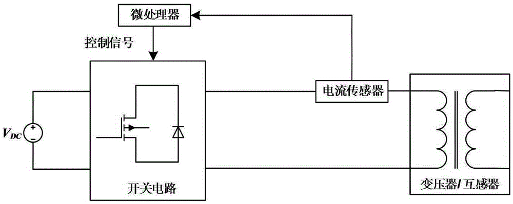
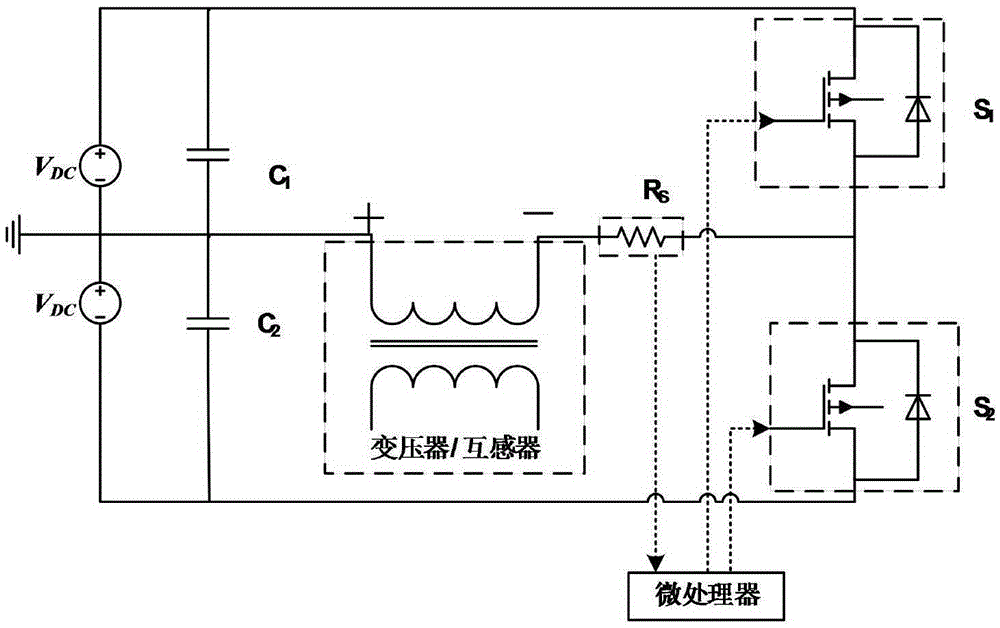
[0031] like figure 1 As shown, the DC voltage source adopts a custom-made voltage adjustable constant voltage source with sufficient power. The switch circuit uses power electronic devices as switches to change the polarity of the DC power supply, and the current sensor uses milliohm-level high-precision non-inductive resistors to reduce losses. The microprocessor mainly controls the switching action according to whether the current in the winding reaches saturation, so as to change the polarity of the voltage applied to both ends of the winding and precisely control its conduction time. Its working process is as follows:

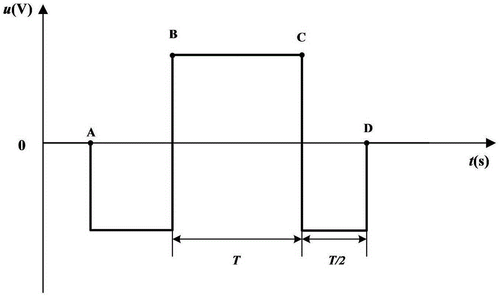
[0032] First, apply a negative DC voltage (-V DC ) to make the iron core reach the negative saturation point; then the microprocessor confirms that the negative saturation current (-I s ), control the switching action, and apply...


PUM


Abstract

The invention provides an iron core remanent magnetism elimination and measurement method based on a polarity-reversal DC voltage source. The iron core remanent magnetism elimination and measurement method is characterized in that the iron core remanent magnetism elimination and measurement method comprises the step 1, applying a negative voltage (-VDC) to enable an iron core to achieve a negative saturation point, and then calculating a winding direct current resistance RDC according to the voltage and current data of the saturation point; and the step 2, changing the power source polarity at two ends of the winding when the current value applied to the winding achieves the negative saturation current (-Is), thus applying a positive direct current voltage (VDC) to the winding to enable the iron core to achieve the positive saturation point, and at the same time recording the time T and the like from the negative saturation point to the positive saturation point. The iron core remanent magnetism elimination and measurement method has the advantages that a single test can measure the remanent magnetism (remanent magnetism coefficient) and eliminate the remanent magnetism; the measuring time is short; the measuring efficiency is high; the demagnetization effect is excellent; the test is simple in operation; and the polarity-reversal direct current source for an electronic power switch is used to realize demagnetization, so that the waveform is well and the power is low and the test cost is low.

Description

technical field [0001] The invention belongs to the technical field of ferromagnetic element iron core residual magnetism elimination and measurement method, and in particular relates to a transformer and transformer residual magnetism elimination method. Background technique [0002] With the continuous improvement of the voltage level of the power grid system, the number of large-capacity power transformers is increasing, which makes industrial applications put forward higher requirements for the reliability and rapidity of electrical equipment protection operation. The accurate measurement of the magnetic properties of electromagnetic materials and the operating conditions of iron core components made of them plays a vital role in the design of electromagnetic devices, calculation of magnetic loss, improvement of operating performance and reliability. [0003] When an external magnetic field is applied to a ferromagnetic substance, the dipoles of its atoms align themselve...

Claims


Application Information

Patent Timeline
IPC IPC(8): G01R33/02H01F13/00
CPCG01R33/02H01F13/006
Inventor 梁仕斌刘鑫刘涛王俊凯彭庆军王磊田庆生姚陈果
Owner 云南电力试验研究院(集团)有限公司
Learn More