
Unmanned aerial vehicle automatic landing locus control method based on double models

A trajectory control and automatic landing technology, applied in the direction of non-electric variable control, attitude control, control/adjustment system, etc., to achieve the effect of easy implementation, fast response and good control effect

Active Publication Date: 2016-03-23
BEIHANG UNIV
View PDF12 Cites 14 Cited by
  • Summary
  • Abstract
  • Description
  • Claims
  • Application Information

AI Technical Summary

Problems solved by technology

The current mainstream control methods are fuzzy PID and dynamic inverse algorithms under the single UAV model, and most of them only use the aspect of UAV attitude control

Method used


Image

  • Unmanned aerial vehicle automatic landing locus control method based on double models
  • Unmanned aerial vehicle automatic landing locus control method based on double models
  • Unmanned aerial vehicle automatic landing locus control method based on double models

Examples


Embodiment Construction

[0085] Below in conjunction with accompanying drawing, each part design method in the present invention is further described:

[0086] The present invention "a kind of UAV automatic landing trajectory control method based on dual models", its specific steps are as follows:

[0087] Step 1: Establish the kinematics and dynamics model of UAV and aircraft carrier

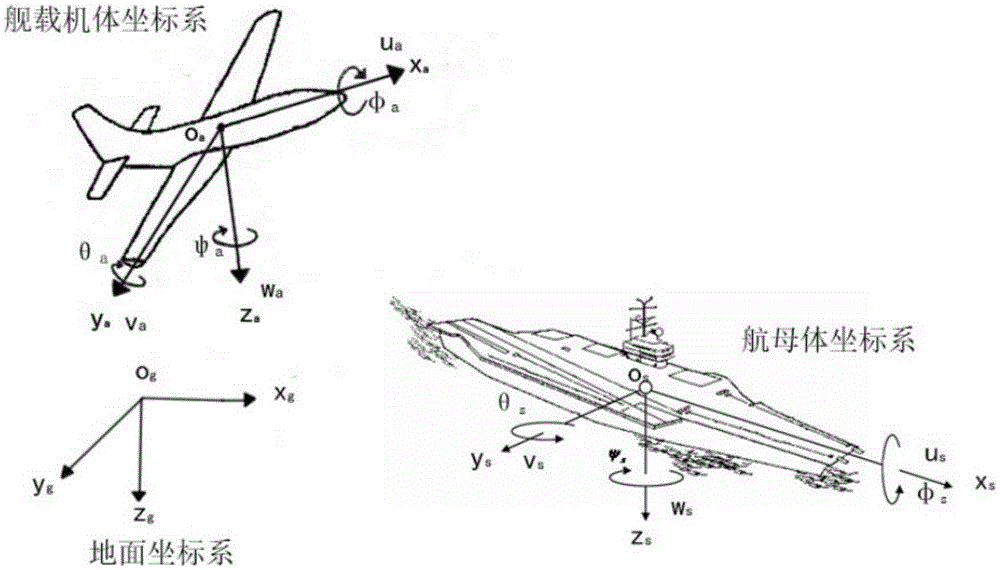
[0088] 1) if figure 1 As shown, the body coordinate system O is established with the UAV center of gravity as the origin a x a the y a z a ; Establish a body coordinate system O with the center of gravity of the aircraft carrier as the origin s x s the y s z s ;Establish an inertial coordinate system O with any point on the ground as the origin g x g the y g z g , where the origin O g is any point on the ground, O g x g pointing north, O g the y g Pointing East, O g z g point to the center of the earth.

[0089] 2) The UAV dynamics model is as follows The aircraft carrier plane dynamics model is a...


PUM


Abstract

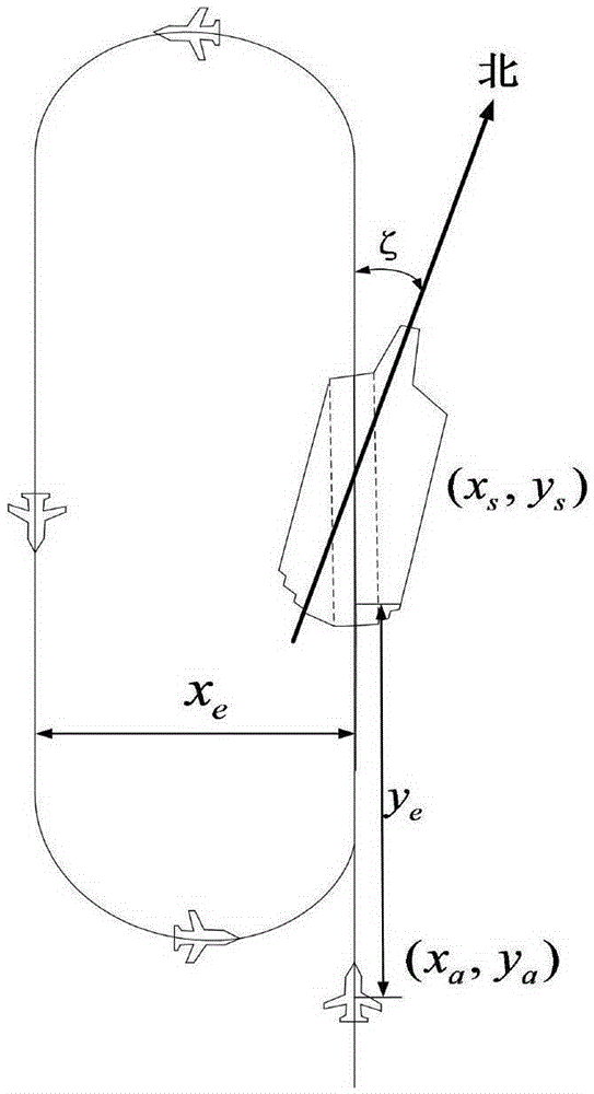
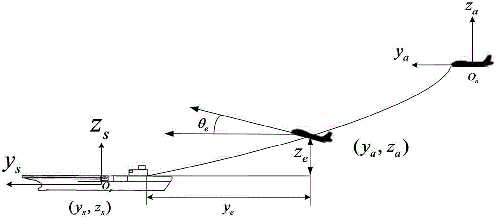
The invention discloses an unmanned aerial vehicle automatic landing locus control method based on double models. The method comprises the following steps: 1, establishing an unmanned aerial vehicle and aircraft carrier dynamical model, and according to relative positions between an unmanned aerial vehicle and an aircraft carrier, establishing a relative movement equation; 2, according to a feedback linearization theoretical method, designing an unmanned aerial vehicle to aircraft carrier locus controller; 3, designing an expected space locus of the aircraft carrier; designing an expected relative tracking value; and designing an expected relative speed; 4, calculating to eliminate errors between expected and actual relative longitudinal (xe<~>), (ue<~>), and transversal (ye<~>)and vertical (ze<~>) relative positions; and calculating to eliminate an error theta e<~> between an expected relative pitch angle and an actual relative pitch angle, a pitch angular speed Pe<~> and a deflection ratio We<~>; and 5, each execution part controlling signal calculation: calculating an execution part control variable [delta T, delta a, delta e, delta r] needed by an execution part control variable u needed for realizing a control amount. A control process is shown in attached drawings.

Description

technical field [0001] The invention provides a trajectory control method for automatic landing of a UAV based on a dual model, which provides a new control method for trajectory control for automatic landing of a UAV, and belongs to the technical field of automatic control. Background technique [0002] Shipborne drones are naval drones based on aircraft carriers or other warships. The control object of this method is a fixed-wing unmanned aerial vehicle. The shipboard UAV with conventional propulsion is a kind of nonlinear mechanical system, and its typical flight states include takeoff, cruising flight, turning, landing, etc. For the automatic landing process of UAVs, most of the current control methods only consider the research on the control laws of UAVs such as isometric glide and deck dynamic compensation based on the UAV's own model control method. This patent proposes a research method for UAV trajectory control based on a new modeling method, that is, not only c...

Claims


Application Information

Patent Timeline
Patent Type & Authority Applications(China)
IPC IPC(8): G05D1/08G05D1/10
CPCG05D1/0808G05D1/101G05D1/0684
Inventor 祝明金正浩郑泽伟孙亮郭宇航
Owner BEIHANG UNIV
Learn More