Power type high-current device mounting process

A high-current, power-type technology, applied in the direction of electric solid-state devices, electrical components, semiconductor devices, etc., can solve the problems of large package chip area, influence on subsequent processing, uneven heat dissipation, etc., achieve uniform solder thickness, prevent oxidation, Effect of improving heat dissipation and reliability

Inactive Publication Date: 2016-03-23
CHANGZHOU GALAXY CENTURY MICROELECTRONICS CO LTD
View PDF4 Cites 4 Cited by
  • Summary
  • Abstract
  • Description
  • Claims
  • Application Information

AI Technical Summary

Problems solved by technology

However, when the chip area of ​​the existing power-type high-current device is greater than 3.0mm, the packaged chip area is relatively large, and the chip is easy to tilt after mounting the chip, resulting in uneven chip mounting and uneven heat dissipation, which affect subsequent processing and client application risks. bad phenomenon

Method used


Image

  • Power type high-current device mounting process

Examples


Embodiment Construction

[0026] In order to make the content of the present invention more clearly understood, the present invention will be further described in detail below based on specific embodiments and in conjunction with the accompanying drawings.

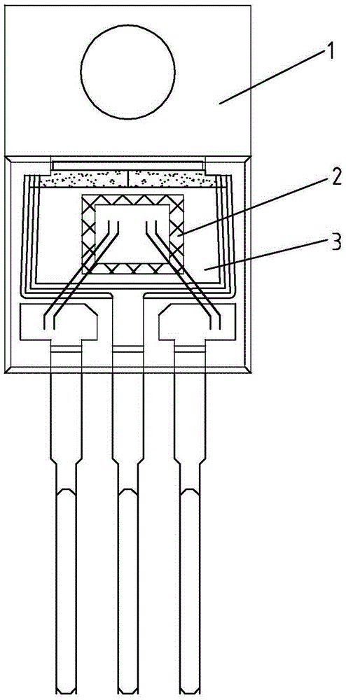
[0027] Such as figure 1 As shown, a power-type high-current device chip mounting process, the process uses a temperature track with a temperature rise area, a temperature stable area and a temperature drop area, and the steps of the process are as follows:

[0028] (a) sending the device frame 1 into the heating area for heat treatment;

[0029] (b) Then the device frame 1 is sent into the temperature stable area, and the solder is spot welded on the PAD area of ​​the device frame 1; the spot welding length of the solder can be selected automatically;

[0030] (c) In the temperature stable area, use a die head to trim the solder on the PAD area of ​​the device frame 1 into a "mouth"-shaped structure with a certain height that matches the chip size...


PUM


Abstract

The invention discloses a power type high-current device mounting process. The process adopts a temperature track provided with a temperature rising region, a temperature stabilizing region and a temperature reducing region; the process comprises the following steps: (a) moving a device framework to the temperature rising region, and heating the device framework in the temperature rising region; (b) then moving the device framework to the temperature stabilizing region, and welding solder on a PAD region of the device framework through a spot welding manner; (c) finishing the solder on the PAD region of the device framework into square-structured solder that is matched with a chip size and has a certain height by using a pressing die in the temperature stabilizing region; (d) placing the chip in the PAD region of the device framework in the temperature stabilizing region to enable the metal and the solder on the back surface of the chip to be co-melted in a temperature environment to form alloy so as to obtain a semifinished product; and (e) moving the semifinished product to the temperature reducing region, and enabling the alloy between the chip and the device framework to be cured in the temperature reducing region. According to the power type high-current device mounting process, the processing quality and the reliability level of the product can be improved, the invalidation rate of clients can be reduced, and the service life of the power type high-current device can be improved.

Description

technical field [0001] The invention relates to a chip loading process of a power type high current device. Background technique [0002] At present, with the continuous advancement of power-type high-current device technology, the size of power-type high-current devices is required to be smaller and smaller, but the processing speed and power requirements are getting higher and higher. However, when the chip area of ​​existing power-type high-current devices is greater than 3.0mm, the packaged chip area is relatively large, and the chip is easy to tilt after mounting, resulting in uneven chip mounting and uneven heat dissipation, which will affect subsequent processing and client application risks. adverse phenomena. Contents of the invention [0003] The technical problem to be solved by the present invention is to overcome the defects of the prior art, and provide a power type high-current device chip loading process, which can improve the quality and reliability of th...

Claims


Application Information

Patent Timeline
Patent Type & Authority Applications(China)
IPC IPC(8): H01L21/48H01L21/50
CPCH01L21/4825H01L21/4842H01L21/50H01L2224/48247H01L2224/49111H01L2224/73265
Inventor 徐青青
Owner CHANGZHOU GALAXY CENTURY MICROELECTRONICS CO LTD
Why Eureka
Try Eureka