Mode-locked fiber laser and pulse laser generation method

A technology of fiber lasers and mode-locked lasers, which is applied to lasers, laser components, phonon exciters, etc., can solve the problems of complex structure, maintenance-free and poor reliability, and achieve simple structure, reliability, maintenance-free, and easy engineering application Effect

Inactive Publication Date: 2016-03-23
LASER FUSION RES CENT CHINA ACAD OF ENG PHYSICS
View PDF8 Cites 15 Cited by
  • Summary
  • Abstract
  • Description
  • Claims
  • Application Information

AI Technical Summary

Problems solved by technology

However, although such methods can realize the engineering application of mode-lock

Method used


Image

  • Mode-locked fiber laser and pulse laser generation method
  • Mode-locked fiber laser and pulse laser generation method
  • Mode-locked fiber laser and pulse laser generation method

Examples


no. 1 example

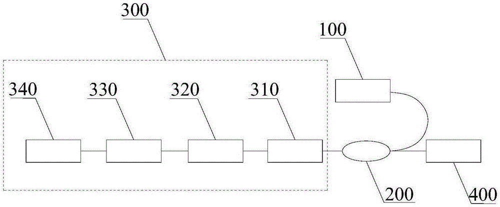
[0036] An embodiment of the present invention provides a mode-locked fiber laser for outputting pulsed laser light, including: a pump source 100 and a mode-locked laser resonator 300 . Such as figure 1 As shown, the mode-locked laser resonator 300 further includes a reflection component 310 , a gain fiber 320 , a polarization-maintaining filter 330 and a saturable absorber mirror 340 for mode-locking, which are sequentially coupled.

[0037]The reflective component 310 and the saturable absorbing mirror 340 are used to make the signal light generated by the gain fiber 320 oscillate multiple times in the mode-locked laser resonator 300 to output the mode-locked pulse laser. Wherein, the reflecting part 310 is mainly used for outputting the mode-locked pulsed laser, outputting a part of the mode-locked pulsed laser, and reflecting the other part back into the mode-locked laser resonator 300 to continue to oscillate. For example, a fiber grating or a laser output mirror can be us...

no. 2 example

[0050] Such as Figure 4 As shown, the embodiment of the present invention provides a pulsed laser generation method, which is applied to the mode-locked fiber laser provided in the first embodiment above, and the method includes:

[0051] Step S401: the gain fiber generates signal light according to the pump light emitted by the pump source, and outputs the signal light to the polarization maintaining filter;

[0052] Step S402: the polarization-maintaining filter processes the received signal light into signal light with a preset polarization direction and a preset wavelength range and outputs it to a saturable absorbing mirror;

[0053] Step S403: The saturable absorber performs mode-locking on the signal light in the preset polarization direction and preset wavelength range, and then transmits it to the polarization-maintaining filter;

[0054] Step S404: the gain fiber amplifies the signal light output by the polarization maintaining filter and transmits it to the reflec...


PUM


Abstract

The invention provides a mode-locked fiber laser and a pulse laser generation method, and belongs to the field of a fiber laser. The mode-locked fiber laser comprises a pumped source and a mode-locked laser resonator, and the mode-locked laser resonator comprises a reflection part, a gain fiber, a polarization-maintaining filter and a saturable absorption mirror which are successively coupled, wherein the saturable absorption mirror is used for mode locking. Pump light emitted by the pumped source penetrates into the gain fiber to generate signal light, the signal light penetrates into the saturable absorption mirror after being processed into signal light in a preset polarization direction and within a preset wavelength scope by the polarization-maintaining filter and returns to the polarization-maintaining filter after mode locking of the saturable absorption mirror, the signal light returning to the polarization-maintaining filter re-penetrates into the gain fiber and is input to the reflection part after being amplified by the gain fiber, and the portion, which meets the transmission condition of the reflection part, in the signal light amplified by the gain fiber is output. Compared to a conventional mode-locked fiber laser, the mode-locked fiber laser provided by the invention is simple in structure and high in stability and reliability, thereby facilitating engineering application.

Description

technical field [0001] The invention relates to the field of fiber lasers, in particular to a mode-locked fiber laser and a method for generating pulsed lasers. Background technique [0002] As the front-end seed source of the ultrashort pulse laser system, the mode-locked fiber laser is the key to the ultrashort pulse laser system, and its basic performance index and stability index directly affect the stability and reliability of the system. Among them, the self-starting and maintenance-free function of the mode-locked fiber laser is an inevitable requirement for its industrialization. Self-starting means that the mode-locked laser can be started immediately after power-on, and output mode-locked pulses. Maintenance-free means that the mode-locked laser can realize mode-locked pulse output in various complex environments, such as high temperature, low temperature, vibration, high humidity and other harsh environments. The current mode-locked fiber laser generally adopts ...

Claims


Application Information

Patent Timeline
IPC IPC(8): H01S3/067H01S3/098
CPCH01S3/067H01S3/1106
Inventor 赵磊李超黎玥梁小宝徐振源封建胜张昊宇周泰斗温静王建军景峰
Owner LASER FUSION RES CENT CHINA ACAD OF ENG PHYSICS
Why Eureka
Try Eureka