Magnetic cam driving unit, vibration table device and linear driving device

A driving unit and cam technology, applied in the direction of electromechanical devices, electrical components, electric components, etc., can solve the problems of poor control accuracy, low energy utilization rate, complex structure, etc., and achieve large driving torque, high energy utilization rate and simple structure Effect

Active Publication Date: 2016-03-23
SHANGHAI JIAO TONG UNIV
View PDF7 Cites 8 Cited by
  • Summary
  • Abstract
  • Description
  • Claims
  • Application Information

AI Technical Summary

Problems solved by technology

The shortcomings of the existing technology are: complex structure, low energy utilization rate, and poor control accuracy

Method used


Image

  • Magnetic cam driving unit, vibration table device and linear driving device
  • Magnetic cam driving unit, vibration table device and linear driving device
  • Magnetic cam driving unit, vibration table device and linear driving device

Examples


no. 1 example

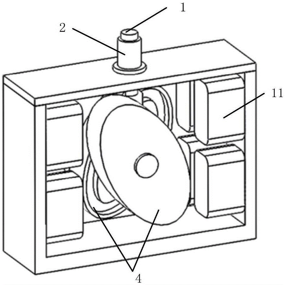
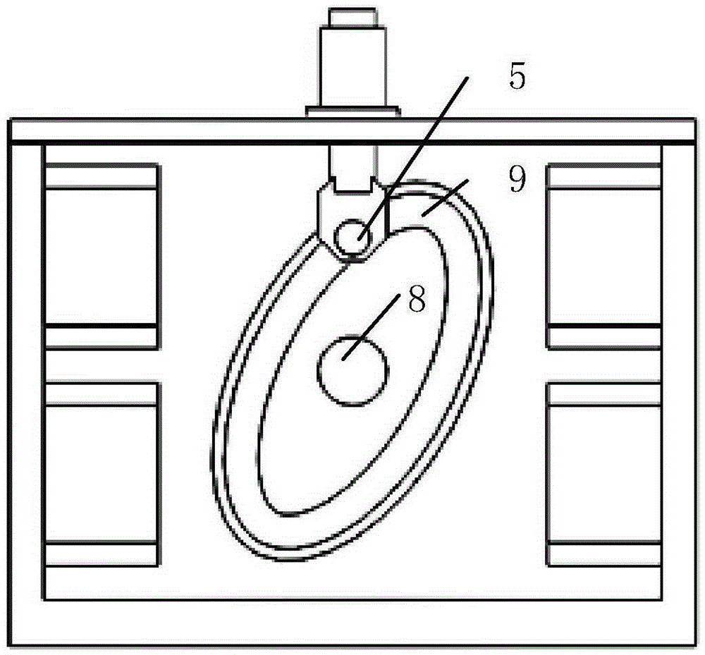
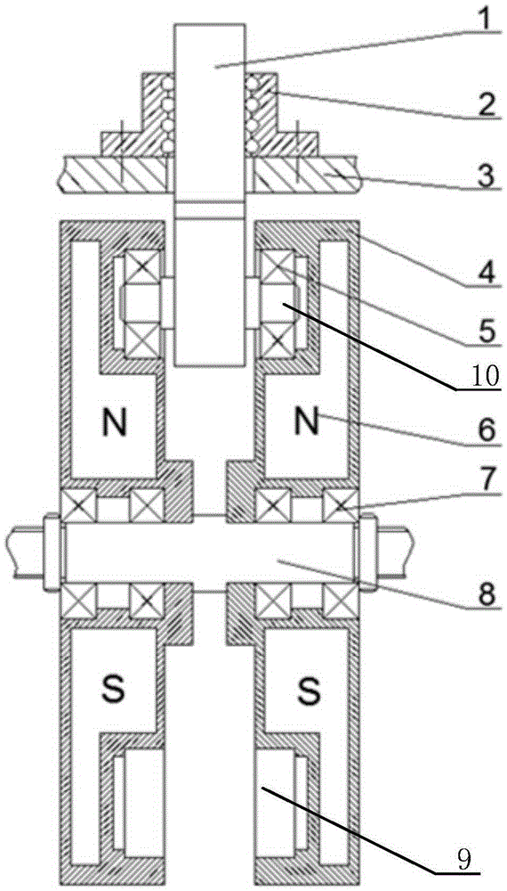
[0076] The first embodiment of the present invention is a preferred example of the basic embodiment. like Figure 1 to Figure 6 As shown, in this embodiment, the cam adopts a pair of conjugated cams; the pair of conjugated cams rotates around the cam support shaft, and are respectively equipped with first magnets (permanent magnets); the pair of conjugated cams The opposite surfaces are respectively provided with annular grooves with consistent contours; one end of the push rod is provided with a push rod support shaft, and two groove bearings are respectively installed on both ends of the push rod support shaft, and the two groove bearings are respectively arranged In the respective annular grooves of the pair of conjugated cams; the grooved bearings can only move along the annular grooves; the push rod is guided by the linear bearings fastened on the support plate; in the pair of conjugated cams Under the magnetic force exerted by the second magnet, the two conjugate cams c...

no. 2 example

[0082] The second embodiment of the present invention is a preferred example of the basic embodiment. like Figure 9 , Figure 10 As shown, in this embodiment, one end of the push rod is connected to the roller, and the curved surface profile of the cam drives the push rod through the roller; the first magnet includes one or more permanent magnets; the second magnet includes a plurality of electromagnets, wherein, more Each electromagnet has an independent power supply circuit, that is, multiple electromagnets can apply magnetic force to the first magnet alone; the permanent magnet is flat, and multiple electromagnets are arranged on one side or both sides of the permanent magnet; the first magnet, the second The two magnets interact to form a magnetic circuit structure. Under the overall excitation of the plurality of electromagnets, the first magnet rotates from an angle corresponding to a smaller magnetic flux in the magnetic circuit structure to an angle corresponding to ...

no. 3 example

[0087] The third embodiment of the present invention is a preferred example of the basic embodiment, and also a modification example of the second embodiment. In this embodiment, the number of first magnets and second magnets is one or more groups; in each group of first magnets and second magnets, the number of electromagnets located on either side of the first magnet is equal to the number of permanent magnets. quantity. A plurality of permanent magnets are evenly distributed in the circumferential direction; a plurality of electromagnets are evenly distributed in the circumferential direction.

[0088] Specifically, the first magnet and the second magnet can adopt various methods. like Figure 15 , Figure 16 , Figure 17 Shown is the arrangement of multiple permanent magnets in a single plane. This arrangement allows multiple permanent magnets to be simultaneously stressed in different orders during the rotation of the cam, making the rotation of the cam more stable an...


PUM


Abstract

The invention provides a magnetic cam driving unit, a vibration table device and a linear driving device. The magnetic cam driving unit comprises a cam, a push rod, first magnetic bodies and second magnetic bodies; the first magnetic bodies are fixedly arranged on the cam; the second magnetic bodies apply a magnetic force to the first magnetic bodies; and after rotating, the cam drives the push rod to move. According to the magnetic cam driving unit of the invention, an electromagnetic mode and a permanent magnet mode are combined, and therefore, energy utilization rate is high; and when a moving part is permanent magnets, structures such as an electric brush do not require to be electrified, and therefore, structural simplicity can be realized; a direct driving mode is adopted, and a driving torque is large; the number of the permanent magnets and electromagnetic coils and position combination relations between the permanent magnets and the electromagnetic coils can be set flexibly, so that an output torque can be improved; and geometric locking is realized structurally, so that components such as the push rod, will not be bounced in high-speed and high-frequency reciprocating motion.

Description

technical field [0001] The invention relates to a cam drive, in particular to a magnetic cam drive unit, a vibrating table device and a linear drive device. Background technique [0002] The vibration table device can be used to simulate various vibration environments encountered by the product during the manufacturing, assembly, transportation and use execution stages, so as to detect the impact of the vibration environment on various parameters of the product. For example, the patent literature (application number 201310091900.7; publication number CN103182728A) discloses a hydraulic vibration table, including a fixed steel frame, a lifting steel frame, a vibration table surface and a hydraulic system. It is the carrier for the lifting of the trolley, and it is assembled in the middle of the fixed steel frame. The jacking cylinder of the hydraulic system is installed between the lifting steel frame and the fixed steel frame, and the vibrating table is installed on the fixe...

Claims


Application Information

Patent Timeline
Patent Type & Authority Applications(China)
IPC IPC(8): H02K7/06H02K7/075
CPCH02K7/061H02K7/075
Inventor 杨斌堂曹逢雨何泉
Owner SHANGHAI JIAO TONG UNIV
Why Eureka
Try Eureka