Tape discharging mechanism and tape attaching device

A technology of discharging mechanism and tape, applied in lamination device, thin material processing, transportation and packaging, etc., can solve the problems of high precision of narrow tape attachment, difficult operation of narrow tape, and increase of product defect rate, etc. The effect of saving demand space, good market prospect and high attachment accuracy

Inactive Publication Date: 2016-03-30
BOE OPTICAL SCI & TECH +1
View PDF2 Cites 6 Cited by
  • Summary
  • Abstract
  • Description
  • Claims
  • Application Information

AI Technical Summary

Problems solved by technology

[0004] 1. The attached narrow tape mainly adopts the form of sheet material structure, which is cut and attached manually by technicians. The labor cost is high, the work efficiency is low, and it is not conducive to the layout of the production line;
[0005] 2. In the process of cutting narrow tapes, it is very difficult for technicians to manually cut narrow tapes, and the narrow tapes are damaged and wasted seriously;
[0006] 3. In the process of attaching narrow tapes, the precision requirements for attaching narrow tapes are high, and the probability of failure to meet the requirements after manual attachment by technicians is high. Reattaching will cause damage to the narrow tapes, and at the same time increase the defective rate of the product

Method used


Image

  • Tape discharging mechanism and tape attaching device
  • Tape discharging mechanism and tape attaching device
  • Tape discharging mechanism and tape attaching device

Examples


Embodiment 1

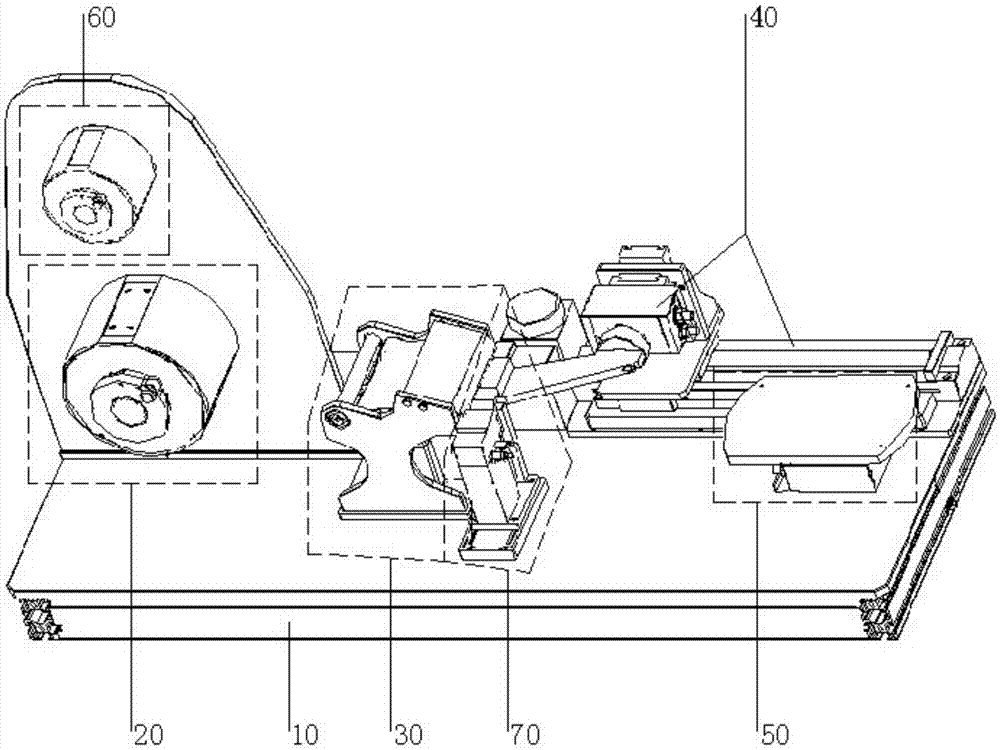
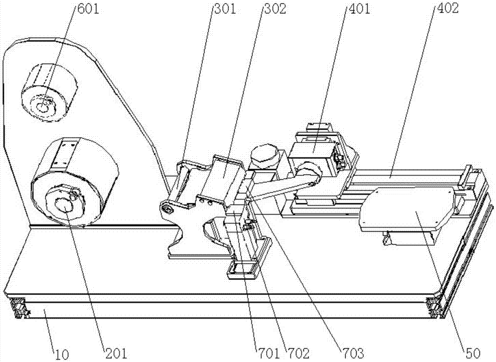
[0048] This embodiment provides an adhesive tape discharging mechanism, which can automatically complete the tape discharging process with high efficiency and high precision by using a coiled material tape in the form of a coiled material structure. The reel tape mentioned here includes a protective film and an adhesive tape, and the protective film covers the adhesive side of the adhesive tape to protect the adhesive performance of the adhesive tape.

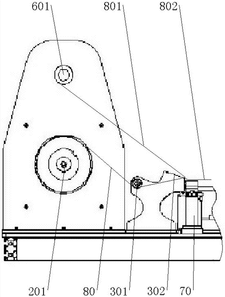
[0049] The adhesive tape discharge mechanism includes a machine table, a coil tape discharge unit and a protective film peeling unit arranged above the machine table, wherein:

[0050] The coil belt discharge unit includes a discharge air-inflating shaft, which is arranged at a relatively front position above the machine table, and is used for rotatingly conveying the coil material belt;

[0051] The protective film peeling unit is arranged at the relative rear of the coil belt discharge unit, and is used for peeling the protec...

Embodiment 2

[0070] This embodiment provides a tape sticking device, the tape sticking device includes a manipulator and the tape discharge mechanism in Embodiment 1, the manipulator is used to attach the tape delivered by the tape discharge mechanism to the surface of the product to be tape .

[0071] The adhesive tape attaching device uses a manipulator to attach the adhesive tape, so that the attachment accuracy is high and the stability is good, and the problems of low manual attachment accuracy, poor stability, serious tape waste, and high product defect rate are solved.

[0072] Tests have shown that the time range for the existing manual sticking of each tape is about 8 to 9 seconds, and the time for sticking each tape with the tape sticking device of this embodiment is about 3.5 seconds, compared with the traditional manual sticking way, the efficiency has been increased by more than 2 times, and the problems of low accuracy, poor stability, serious tape waste and high product defe...


PUM

PropertyMeasurementUnit
widthaaaaaaaaaa

Abstract

The invention provides a tape discharging mechanism and a tape attaching device, which belong to the technical field of displays, and can solve the problem that the efficiency is low and the cost is high due to the fact that the tape is manually cut and attached to assemble backlight products in the prior art. The tape discharging mechanism comprises a coil stock tape discharging unit and a protective film stripping unit, wherein the coil stock tape discharging unit comprises a discharge air swelling shaft used for rotationally transporting the coil stock tape; the protective film stripping unit is arranged at the rear opposite to the coil stock tape discharging unit, is used for stripping the protective film from the tape, and transporting the tape. The tape discharging mechanism realizes an automatic discharging and stripping process of the coil stock tape, and the problems of low operation efficiency and high cost due to manual operation are solved. The tape attaching device comprises a manipulator and the tape discharging mechanism, can further complete a process of automatic tape attaching, the efficiency and precision of attaching are further improved, and the cost is reduced.

Description

technical field [0001] The invention belongs to the field of display technology, and in particular relates to a tape discharging mechanism and a tape attaching device. Background technique [0002] With the rapid development of the electronics industry, the market share of ultra-thin electronic products continues to increase, and the assembly process of backlight products is also changing day by day. In the traditional backlight product assembly process, technicians manually cut the narrow tape, and then stick it on the corresponding position of the backlight product, and then complete the assembly of the backlight product one after another. The narrow tapes here are usually narrow tapes in the form of sheets, and in the current actual production, the width of the narrow tapes used is becoming narrower and narrower. Similarly, the precision requirements for the attachment of the narrow tapes are also increasing. high. [0003] The inventor finds that there are at least the...

Claims


Application Information

Patent Timeline
Patent Type & Authority Applications(China)
IPC IPC(8): B32B38/10B32B37/10B32B38/18B65H16/04
CPCB32B37/10B32B38/10B32B38/18B32B2038/1891B65H16/04B65H2701/19
Inventor 褚福流朱家伟
Owner BOE OPTICAL SCI & TECH
Why Eureka
Try Eureka