
Slag waste heat recovery and utilization device

A waste heat recovery and slag technology, applied in furnaces, waste heat treatment, furnace components, etc., can solve problems such as heat waste, no equipment structure design, difficult equipment use state control, etc., to increase heat exchange area, increase heat exchange effect, The effect of improving the heat exchange effect

Active Publication Date: 2017-07-25
SINOHYDRO BUREAU 8 CO LTD
View PDF7 Cites 0 Cited by
  • Summary
  • Abstract
  • Description
  • Claims
  • Application Information

AI Technical Summary

Problems solved by technology

However, the existing devices used to recycle the waste heat of slag have very low utilization efficiency, especially the utilization efficiency of waste heat from slag with low calorific value is lower, a large amount of heat carried in the slag is wasted, and directly causes heat pollution to the environment
In addition, the existing slag waste heat utilization device does not have a special structural design for controlling the equipment, which makes it difficult to control the use status of the equipment and fails to fully utilize the slag waste heat

Method used


Image

  • Slag waste heat recovery and utilization device
  • Slag waste heat recovery and utilization device

Examples


Embodiment 1

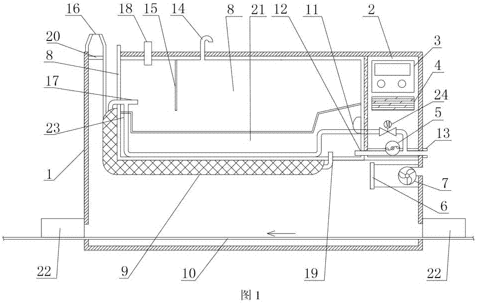
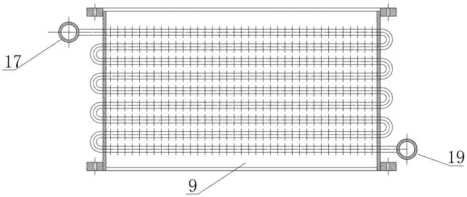
[0033] Such as figure 1 with 2 As shown, the slag waste heat recovery and utilization device of this embodiment includes a body 1, a cold water tank 8 and a hot water tank 21 arranged inside the body 1, a slag conveying channel is provided at the lower part of the body 1, and the hot water tank 21 is arranged on the slag Above the conveying channel, the cold water tank 8 is arranged on the hot water tank 21, and also includes a heat conducting net 9, the heat conducting net 9 is arranged between the slag conveying channel and the hot water tank 21, and the heat conducting net 9 is provided with a heat conducting net water inlet pipe 17 and The heat conduction net water outlet pipe 19, the heat conduction net 9 is connected with the cold water tank 8 through the heat conduction net water inlet pipe 17, and the heat conduction net 9 is connected with the hot water tank 21 through the heat conduction net water outlet pipe 19. Through the setting of the height difference between ...


PUM


Abstract

The invention discloses a slag waste heat recycling device. The slag waste heat recycling device comprises a machine body, a cold water tank and a hot water tank, wherein the cold water tank and the hot water tank are arranged inside the machine body; a slag conveying passage is arranged at the lower part of the machine body; the hot water tank is arranged above the slag conveying passage; the cold water tank is arranged above the hot water tank; the device also comprises a heat conducting net which is arranged between the slag conveying passage and the hot water tank; the heat conducting net is provided with a heat conducting net water charging pipe and a heat conducting net water discharging pipe; the heat conducting net is connected with the cold water tank via the heat conducting net water charging pipe and is connected with the hot water tank via the heat conducting net water discharging pipe. The slag waste heat recycling device disclosed by the invention is high in utilization efficiency of slag waste heat, simple in structure, convenient to operate and maintain, high in adaptability, good in economical efficiency and low in pollution.

Description

technical field [0001] The invention belongs to the field of waste heat recovery and utilization equipment, and in particular relates to a slag waste heat recovery and utilization device. Background technique [0002] A large amount of slag is produced in the production process of various industrial furnace equipment. These slags are often accompanied by a large amount of waste heat. According to calculations from technical data, this part of waste heat resources accounts for more than 17% of its fuel consumption. It can be seen that the utilization of slag waste heat is huge. potential. The utilization of waste heat from slag can not only reduce energy consumption per unit of product, but also reduce environmental pollution. Therefore, the utilization of waste heat from slag has considerable economic and social benefits. However, the existing devices for recycling slag waste heat have very low utilization efficiency, especially low heat value slag waste heat utilization ef...

Claims


Application Information

Patent Timeline
Patent Type & Authority Patents(China)
IPC IPC(8): F27D17/00
CPCF27D17/004Y02P10/25
Inventor 夏敏
Owner SINOHYDRO BUREAU 8 CO LTD
Learn More