Optical fiber grating temperature sensor wavelength shift correction method and temperature measuring device

A technology of temperature sensor and wavelength shift, which is used in measurement devices, thermometer testing/calibration, thermometers, etc. It can solve the problems of inapplicable application requirements, increased errors, and large amount of calculation, so as to reduce the amount of calculation and expand temperature measurement. Effects with high range and real-time performance

Inactive Publication Date: 2016-03-30
UNIV OF JINAN +1
View PDF4 Cites 8 Cited by
  • Summary
  • Abstract
  • Description
  • Claims
  • Application Information

AI Technical Summary

Problems solved by technology

[0003] The quadratic fitting method is generally calibrated in the middle and low temperature area, so the quadratic fitting method has better accuracy in the middle and low temperature area, and the error is within 0.2°C, but in the middle and high temperature area (above 60°C), the error gradually increases
[0004] The existing fitting method is the quadratic or cubic fitting of the temperature T. After detecting λ, it is necessary to solve the equation to obtain T. The calculation amount is relatively large, and the implementation is relatively complicated. A single device can be used to achieve large capacity (multiple temperature measurement points) ), high real-time temperature measurement requirements, high cost, not suitable for cost-effective, large-capacity (multiple temperature measurement points) application requirements

Method used


Image

  • Optical fiber grating temperature sensor wavelength shift correction method and temperature measuring device
  • Optical fiber grating temperature sensor wavelength shift correction method and temperature measuring device
  • Optical fiber grating temperature sensor wavelength shift correction method and temperature measuring device

Examples


Embodiment Construction

[0029] The present invention will be further described below in conjunction with the accompanying drawings and embodiments.

[0030] A fiber grating temperature sensor wavelength offset correction method, using the wavelength offset cubic fitting method for correction, the fitting formula is:

[0031] T=K 0 +K 1 Δλ+K 2 Δλ 2 +K 3 Δλ 3 (1)

[0032] Among them: T is the measured temperature, Δλ is the wavelength shift relative to a reference reflection wavelength, K 0 、K 1 、K 2 、K 3 is a constant and requires actual calibration.

[0033] Based on the center wavelength of the reflected wave at 0°C, the fitting formula is:

[0034] T=K 1 Δλ+K 2 Δλ 2 +K 3 Δλ 3 (2)

[0035] Where: Δλ is the center wavelength shift of the reflected wave relative to the reflected wave at 0°C.

[0036] The existing quadratic fitting formula is:

[0037] λ=a+bT+cT 2 (3)

[0038] Among them: λ is the wavelength of the reflected wave, T is the measured temperature, a, b, and c are cons...


PUM


Abstract

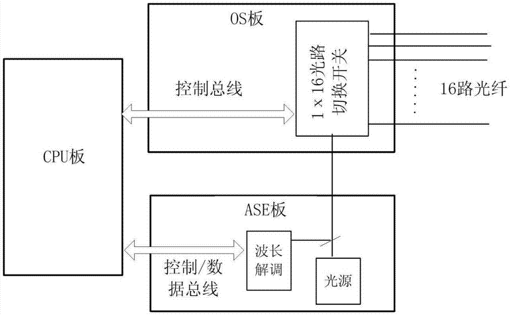
The invention discloses an optical fiber grating temperature sensor wavelength shift correction method and a temperature measuring device. Correction is conducted by a wavelength shift cubic fitting method, and the fitting formula is as follows: T=K0+K1*delta(lambda)+K2*delta(lambda<2>)+K3*delta(lambda<3>), wherein T is measured temperature, delta(lambda) is wavelength shift relative to a benchmark reflection wavelength, and K0, K1, K2 and K3 are constants and need to be actually calibrated. The temperature measuring device comprises a CPU board which is connected with an OS board; the OS board is connected with multi channels of optical fibers; each channel of optical fiber is connected in series with multiple temperature measuring gratings; the OS board is further connected with an ASE board; and the ASE board is equipped with a wavelength demodulation module and a light source. The wavelength shift cubic fitting method can help to decrease the amount of calculation of temperature fitting significantly, and is easy to implement. The temperature T is calculated out directly after delta(lambda) is detected, and the real-time performance of temperature calculation is improved. By using the wavelength shift cubic fitting method put forward by the invention, the error of an optical fiber grating at 140 DEG C can be controlled within 2 DEG C.

Description

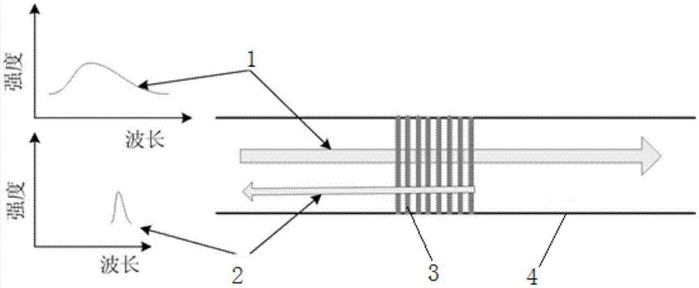
technical field [0001] The invention relates to the technical field of optical fiber grating temperature sensor correction, in particular to a method for correcting wavelength offset of an optical fiber grating temperature sensor and a temperature measuring device. Background technique [0002] The fiber grating temperature sensor has the advantages of compact structure, small size, anti-electromagnetic interference, and non-electricity. It has been widely used in high voltage, strong interference, strong corrosion, and explosion-proof occasions such as electric power, petroleum, chemical industry, coal, and fire protection. Form, precision correction and other technologies are still in constant development. The fiber grating temperature sensor is composed of grating, optical fiber, light source, detection circuit, etc., and its optical path principle is as follows: figure 1 As shown, when a beam of wide-spectrum light passes through a fiber grating, the wavelengths satisfy...

Claims


Application Information

Patent Timeline
Patent Type & Authority Applications(China)
IPC IPC(8): G01K15/00G01K11/32G01K11/3206
CPCG01K11/3206G01K15/005
Inventor 王成友邓亚军魏鹏薛海军程新功刘益青宗西举任宏伟于春光
Owner UNIV OF JINAN
Why Eureka
Try Eureka