Check patentability & draft patents in minutes with Patsnap Eureka AI!

A pulsed laser ranging detector apd adjustment circuit

A pulsed laser ranging and circuit adjustment technology, applied in the field of photoelectric detection, can solve the problems of small voltage adjustment range, responsible structure, single function, etc., and achieve the effects of wide temperature adaptation range, improved work adaptability, and simple circuit structure

Active Publication Date: 2018-02-27
河南平原光电有限公司
View PDF7 Cites 0 Cited by
  • Summary
  • Abstract
  • Description
  • Claims
  • Application Information

AI Technical Summary

Problems solved by technology

[0002] The pulse laser range finder is a complex, high-tech product that combines optics, electromechanics and electronics. With the aid of sight and sight equipment, it can achieve target measurement within the range of the range. The pulse laser range finder avalanche detector bias APD adjustment circuit is a pulse laser An avalanche detector bias APD adjustment circuit is necessary for the range finder. The performance of the adjustment circuit directly determines the overall performance of the pulse laser range finder. Therefore, in all kinds of pulse laser range finders currently used, All of them are equipped with a bias APD adjustment circuit, but the structure of the currently used bias APD adjustment circuit is relatively responsible, and the temperature adaptability to the surrounding working environment is relatively narrow, and its own voltage adjustment range is relatively small. The ability to quickly and automatically adjust temperature and noise is also relatively poor, the disadvantages of single function and insufficient work flexibility, which greatly limit the working performance of the pulsed laser rangefinder, so it is urgent to develop a new type of bias APD adjustment circuit

Method used


Image

  • A pulsed laser ranging detector apd adjustment circuit

Examples


Embodiment Construction

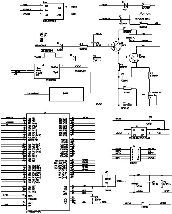
[0012] Such as figure 1 As shown, a pulse laser ranging detector APD adjustment circuit is composed of a high-voltage circuit, a detection circuit, a signal feedback circuit, a data processing circuit and a positive temperature compensation circuit. The data processing circuit is connected to the high-voltage circuit, and one of the signal feedback circuits is enlarged The circuit is connected to the detection circuit, and the signal feedback circuit is also connected to the positive temperature compensation circuit. The high-voltage circuit is composed of a voltage adjustment module LHS1-24S600EB, adjustment resistors R2, R3, energy storage capacitor C7 and an induction coil L2. The detection circuit is composed of a detection module U0 And the signal amplification module NotLaserSignal is connected, the signal feedback circuit is composed of two amplification circuits composed of two triodes Q2 and Q3, and the amplification circuit composed of the triode Q3 is also connected ...


PUM


Abstract

The invention discloses an APD adjustment circuit of a pulse laser ranging detector, which is composed of a high-voltage circuit, a detection circuit, a signal feedback circuit, a data processing circuit and a positive temperature compensation circuit. The data processing circuit is connected with the high-voltage circuit, and the amplifying circuit is separately connected with the The detection circuit is connected with the signal feedback circuit, and the signal feedback circuit is also connected with the positive temperature compensation circuit. Compared with the traditional bias voltage APD adjustment circuit, the present invention has the characteristics of wide adaptable range of working environment temperature, large self-voltage adjustment range, simple circuit structure, and the circuit can be adjusted quickly and automatically with temperature and noise, with high degree of automation and accurate adjustment value. It also has the functions of temperature compensation, noise feedback, and program-controlled adjustment, which greatly improves the working adaptability, stability, and flexibility of the bias voltage APD adjustment circuit.

Description

technical field [0001] The invention relates to an APD adjustment circuit of a pulsed laser ranging detector, which belongs to the technical field of photoelectric detection. Background technique [0002] The pulse laser range finder is a complex, high-tech product that combines optics, electromechanics and electronics. With the aid of sight and sight equipment, it can achieve target measurement within the range of the range. The pulse laser range finder avalanche detector bias APD adjustment circuit is a pulse laser An avalanche detector bias APD adjustment circuit is necessary for the range finder. The performance of the adjustment circuit directly determines the overall performance of the pulse laser range finder. Therefore, in all kinds of pulse laser range finders currently used, All of them are equipped with a bias APD adjustment circuit, but the structure of the currently used bias APD adjustment circuit is relatively responsible, and the temperature adaptability to t...

Claims


Application Information

Patent Timeline
Patent Type & Authority Patents(China)
IPC IPC(8): G01S17/08
Inventor 曲雅臣李帅陈龙飞张龙李金映李亮马英李会玲韩建军辛玫
Owner 河南平原光电有限公司
Features
  • R&D
  • Intellectual Property
  • Life Sciences
  • Materials
  • Tech Scout
  • Unparalleled Data Quality
  • Higher Quality Content
  • 60% Fewer Hallucinations
Learn More