
Short-wave radio station high-altitude nuclear electromagnetic pulse protection device
A nuclear electromagnetic pulse and short-wave radio technology, applied in circuit devices, emergency protection circuit devices for limiting overcurrent/overvoltage, emergency protection circuit devices, etc., can solve problems such as short-wave communication equipment not considering system survivability, Achieve the effect of improving the protection effect of strong electromagnetic pulse and protecting the receiving circuit
- Summary
- Abstract
- Description
- Claims
- Application Information
AI Technical Summary
Problems solved by technology
Method used
Image

Examples
Embodiment Construction
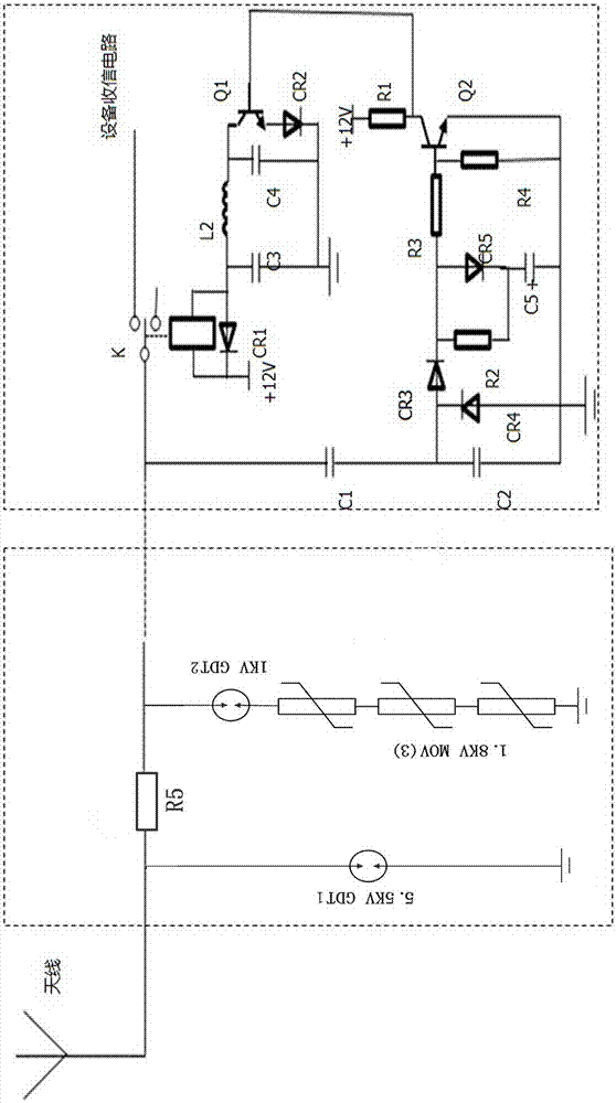
[0022] As shown in the figure, the present invention includes a gas discharge tube GDT1, the key points of the structure are that one end of GDT1 is connected to the antenna and one end of resistor R5, the other end of GDT1 is grounded, and the other end of R5 is respectively connected to one end of gas discharge tube GDT2 and the controlled end of relay K. Terminal, one end of capacitor C1 is connected, the other end of GDT2 is connected to one end of the first varistor, the other end of the first varistor is connected to one end of the second varistor, the other end of the second varistor is connected to one end of the third varistor, The other end of the third varistor is grounded.
[0023] The other end of C1 is connected to one end of capacitor C2, the anode of diode CR3, and the cathode of diode CR4, and the anode of CR4 is connected to the other end of C2, one end of capacitor C5, the ground wire, one end of resistor R4, and the emitters of three NPN transistors Q2.
[...
PUM
| Property | Measurement | Unit |
|---|---|---|
| Resistance | aaaaa | aaaaa |
| Resistance | aaaaa | aaaaa |
| Resistance | aaaaa | aaaaa |
Abstract
Description
Claims
Application Information