
Large-diameter motor stator structure and mounting method thereof

A technology of motor stator and installation method, applied in electromechanical devices, manufacturing motor generators, magnetic circuit shape/style/structure, etc., can solve the problems of low utilization rate of enameled wire winding, easy damage of coil insulation layer, inconvenient coil, etc. , to achieve the effect of convenient winding, high slot full rate and convenient production

Inactive Publication Date: 2016-03-30
杭州桢正机器人科技有限公司
View PDF8 Cites 2 Cited by
  • Summary
  • Abstract
  • Description
  • Claims
  • Application Information

AI Technical Summary

Problems solved by technology

[0004] The present invention mainly solves the technical problems of inconvenient coil winding for the original large-diameter motor stator, small slot fullness rate, low utilization rate of the enameled wire winding, and easy damage to the coil insulation layer; it provides a large-diameter motor stator structure and its installation method, Enameled wire windings are easy to wind, neatly arranged, no need to leave space for wire needles, enameled wire windings are tightly wound, small at the end, high slot filling rate, high utilization rate of enameled wire windings, and the coil insulation layer is not easily damaged, which improves the motor quality and work efficiency

Method used


Image

  • Large-diameter motor stator structure and mounting method thereof
  • Large-diameter motor stator structure and mounting method thereof
  • Large-diameter motor stator structure and mounting method thereof

Examples


Embodiment

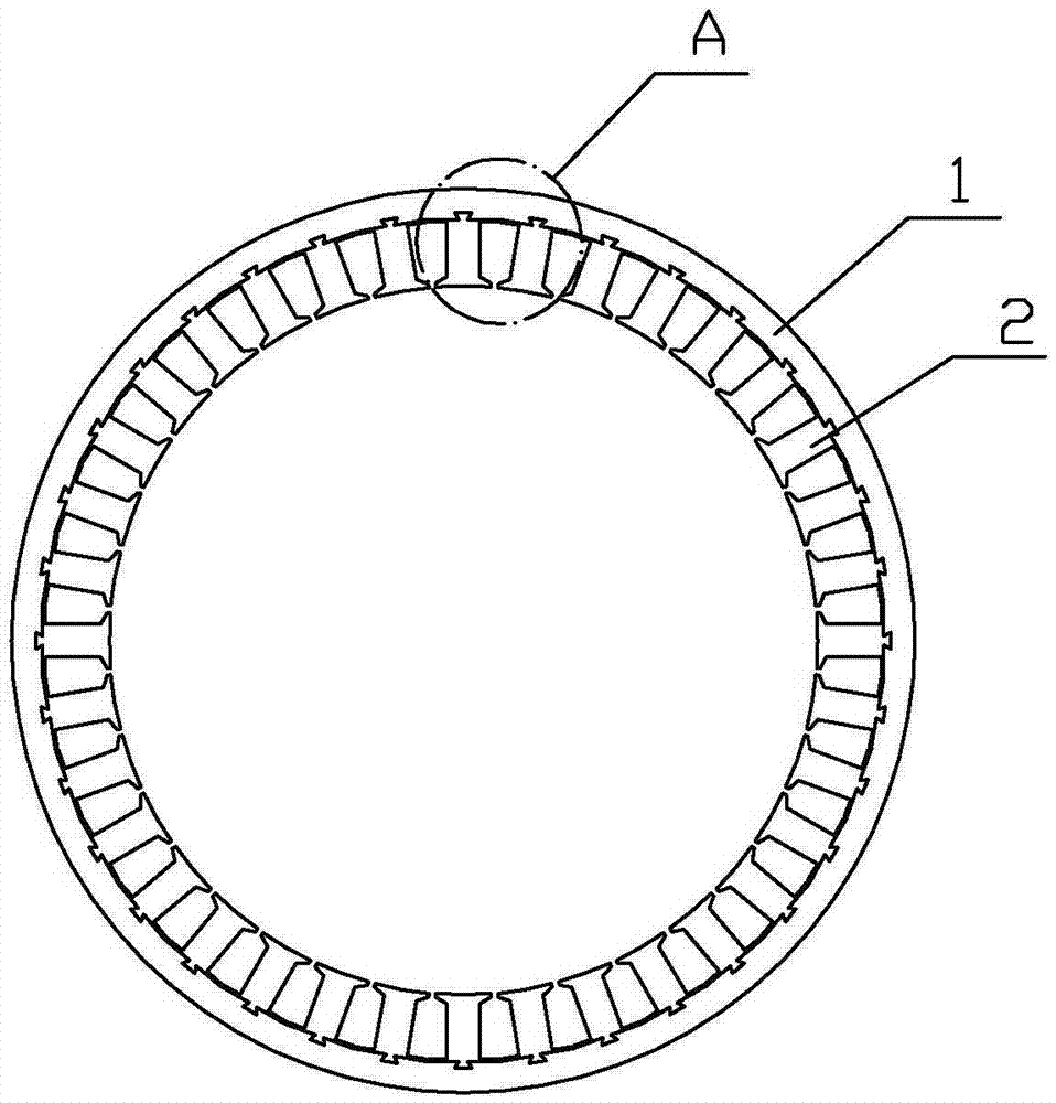
[0024] Embodiment: the large-diameter motor stator structure of the present embodiment, such as image 3 , Figure 4 As shown, it includes a stator core and an enameled wire winding 8, and the stator core includes a yoke body 1 and a plurality of teeth 2 connected to the yoke body 1, such as Figure 5 As shown, the yoke body 1 is in the shape of a tube, and the inner surface of the yoke body 1 has a plurality of slots 3 uniformly distributed along the circumference of the yoke body. The tooth body and the yoke body are two separate and discrete parts. There is a card head 4 matching the card slot 3. In this embodiment, the card slot 3 is a dovetail groove, and the card head 4 is a dovetail tenon head. The dovetail groove extends along the length of the yoke body 1, and the dovetail tenon head extends along the length of the tooth body 2. The connection between the tooth body 2 and the yoke body 1 is realized by embedding the dovetail tenon into the dovetail groove. Such as ...


PUM


Abstract

The invention relates to a large-diameter motor stator structure and a mounting method thereof. The stator structure comprises a yoke body, a plurality of tooth bodies connected with the yoke body, and an enameled wire windings winding around the tooth bodies. A plurality of clamp grooves are formed in the inner side surface of the yoke body; the rear sides of the tooth bodies are provided with clamp heads matching the clamp grooves; and the tooth bodies are clamped into the clamp grooves by the clamp heads and are connected with the yoke body. A blocking shoulder is arranged at each of the two sides of the rear sides of the tooth bodies; a blocking plate is arranged at each of the two sides of the front sides of the tooth bodies; winding slots are formed between the blocking shoulders and the blocking plates; and enameled wire windings wind around the winding slots. In addition, the mounting method includes: an enameled wire winding winds around each tooth body by a winding machine; the tooth bodies wound with the enameled wire windings are embedded into the inner side surface of the yoke body one by one; the clamp heads of the clamp bodies and the clamp grooves of the yoke body are clamped; and the multiple tooth bodies are distributed uniformly along the periphery of the yoke body. According to the invention, winding of the enameled wire windings becomes convenient; the windings are arranged in order; the winding becomes compact; the end part is small; the groove filling rate is high; the utilization rate of the enameled wire winding is high; the coil insulation layer is not easy to damage; and the reliability is improved.

Description

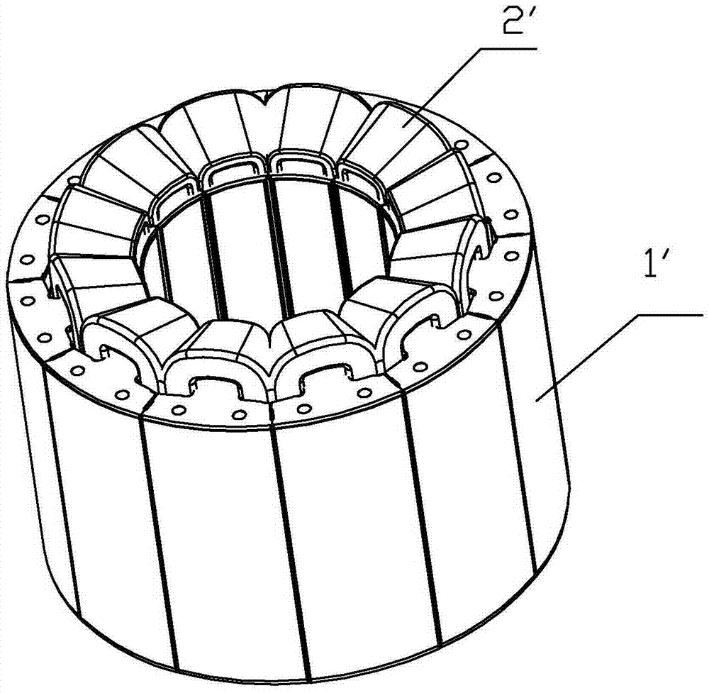
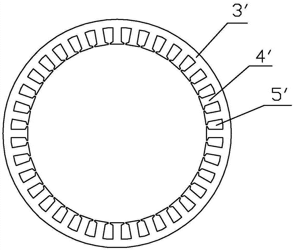
technical field [0001] The invention relates to a motor, in particular to a large-diameter motor stator structure with high coil utilization rate, convenient installation and improved efficiency and an installation method thereof. Background technique [0002] The stator of the motor, such as figure 1 As shown, it consists of a stator core 1' and an enameled wire winding 2' wound on the iron core teeth of the stator core 1'. The stator of a large-diameter motor generally adopts a multi-slot structure, and its stator core is often made of integral punching, such as figure 2 As shown, a plurality of teeth 4' protrude radially from the inner surface of the circular yoke 3', the teeth 4' and the yoke 3' are integral, punched and laminated from silicon steel sheets, the two The space between two adjacent tooth parts 4' is called a slot 5', and the enameled wire winding 2' around a single tooth part is wound in the slot 5'. [0003] For the large-diameter motor stator structur...

Claims


Application Information

Patent Timeline
Patent Type & Authority Applications(China)
IPC IPC(8): H02K1/14H02K15/08
Inventor 叶鹏江思敏金国华李星星齐玙珂
Owner 杭州桢正机器人科技有限公司
Learn More