Non-contact engine turbine blade tip radial gap measurement method

A radial gap, non-contact technology, applied in the direction of measuring devices, instruments, electrical devices, etc., can solve the problems of inability to achieve full-circle measurement, low precision, poor operability, etc.

Inactive Publication Date: 2016-04-06
SHENYANG LIMING AERO-ENGINE GROUP CORPORATION
View PDF4 Cites 17 Cited by
  • Summary
  • Abstract
  • Description
  • Claims
  • Application Information

AI Technical Summary

Problems solved by technology

[0006] In view of the above-mentioned technical problems, the turbine rotor blade tip clearance measurement means has low precision, poor operability, and can not realize the shortcomings of full circumference measurement. The present invention provides a non-contact engine turbine blade tip radial clearance measurement method, which solves the problem of Technical difficulties such as sensor and wire installation, signal conditioning and transmission, and rotor angle synchronous measurement in a narrow space provide a new technical means for improving the assembly accuracy of the aeroengine rotor system

Method used


Image

  • Non-contact engine turbine blade tip radial gap measurement method
  • Non-contact engine turbine blade tip radial gap measurement method
  • Non-contact engine turbine blade tip radial gap measurement method

Examples


Embodiment

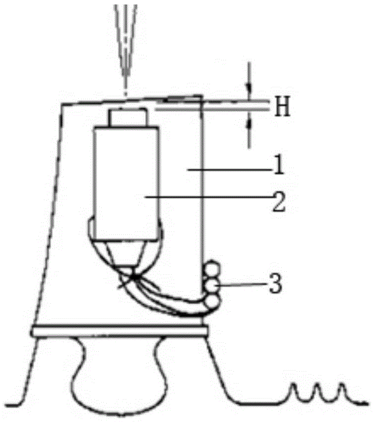
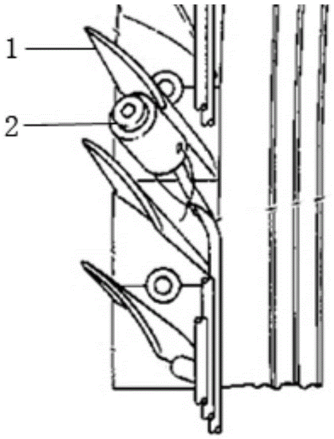
[0026] Embodiment: The high-pressure turbine blade tip radial clearance measurement system is based on the electrostatic capacity non-contact sensor. In order to ensure the surface integrity of the engine parts and the reliability of the sensor installation, the sensor is fixed on the turbine blade with PVC-based acrylic double-sided adhesive that does not damage the metal material, and the positioning surface is added on the side of the sensor head to ensure that the front end is in contact with the blade. The ends are flush. The inner ring surface of the high-pressure turbine casing and the front end of the sensor measuring head constitute the two plates of the capacitor. This capacitance value is a function of the geometry of the two plates, the distance between the plates, and the relative permittivity of the medium between the plates. If the edge effect is not considered, the relationship between the capacitance value and the distance between the two plates can be expres...


PUM


Abstract

A non-contact engine turbine blade tip radial gap measurement method belongs to the gas turbine technology field. The method is characterized by calibrating a sensor and a micrometer before measurement and inputting a curve during protocolling and calibration into a computer; fixing the sensor to any one blade of a high pressure turbine rotor and making an induction end of the sensor and a blade tip flush so as to form a space to be measured H with an inner ring surface of a high pressure turbine case; uniformly fixing coaxial cables connected to the sensor to a turbine rotor and winding at least one circle along an engine rotation direction; fixing an angle rotation encoder to a manual rotating shaft of an engine assembling bench, recording an angle position as a starting position and adjusting a measured initial point; setting an angle ratio i between the rotation encoder and an engine rotation table, rotating the engine rotor through a signal collected by the computer and the manual rotating shaft, observing and recording a blade tip gap value of a current angle position till that the sensor is rotated to an initial position so that case inner ring surface periphery measurement is completed. By using the method, 360 degree gap measurement in the whole case can be realized.

Description

technical field [0001] The invention belongs to the technical field of gas engines, and in particular relates to a non-contact method for measuring the radial clearance of a turbine blade tip of an engine. Background technique [0002] The efficiency of aeroengine compressor and turbine components, the vibration characteristics of rotor components, and the reasonable control of the gap between rotor components and casing coating materials will directly affect the performance level of the whole machine. How to measure and monitor the rotor blade tip clearance within the measurement range of 1-2mm during the assembly of engine components and the operation of the whole machine is a technical problem that aero-engine assembly and manufacturing organizations at home and abroad have devoted a lot of energy to research. [0003] Reasonable control of the gap between the high-pressure turbine rotor and the main combustion chamber combined unit body of the high-pressure turbine outer...

Claims


Application Information

Patent Timeline
Patent Type & Authority Applications(China)
IPC IPC(8): G01B7/14
CPCG01B7/14
Inventor 阴松凯贾超波辛彦秋万利韩迪
Owner SHENYANG LIMING AERO-ENGINE GROUP CORPORATION
Why Eureka
Try Eureka