Compression perception radar high resolution imaging equipment under low signal to noise ratio and imaging method thereof

A technology of compressed sensing and low signal-to-noise ratio, which is applied in the directions of radio wave reflection/re-radiation, utilization of re-radiation, and measurement devices, which can solve the problem of low longitudinal resolution of low-frequency narrow-band ultrasonic detectors, large time loss of SAR images, and inability to Obtain integrity and other issues to achieve the effect of solving the impact of noise on imaging quality, improving imaging resolution, and suppressing noise and side lobes

Inactive Publication Date: 2016-04-06
SHANGHAI RADIO EQUIP RES INST
View PDF10 Cites 19 Cited by
  • Summary
  • Abstract
  • Description
  • Claims
  • Application Information

AI Technical Summary

Problems solved by technology

This method will broaden the main lobe of the target while suppressing the side lobes of the target, and the imaging effect on the high frequency part of the imaging scene is poor.
[0006] Authorized patent CN104111458A "Compressed Sensing Synthetic Aperture Radar Imaging Method Based on Double Sparse Constraints", published on October 22, 2014, this method is used to solve the problem that the traditional synthetic aperture radar imaging method cannot obtain a complete SAR image and the time loss is large when downsampling This method can obtain better imaging results when there is no noise, but when the signal-to-noise ratio is weak, the echoes of the target scene are "submerged" in the noise, which affects the imaging quality
[0007] Authorized patent CN102279394B "Low-frequency narrow-band high-resolution ultrasonic detection and imaging method", the publication date is June 26, 2013. This method mainly solves the problem of low longitudinal resolution of low-frequency narrow-band ultrasonic detectors. Due to the differences between ultrasonic imaging and radar imaging processes , this method is not suitable for high-resolution radar imaging process

Method used


Image

  • Compression perception radar high resolution imaging equipment under low signal to noise ratio and imaging method thereof
  • Compression perception radar high resolution imaging equipment under low signal to noise ratio and imaging method thereof
  • Compression perception radar high resolution imaging equipment under low signal to noise ratio and imaging method thereof

Examples


Embodiment Construction

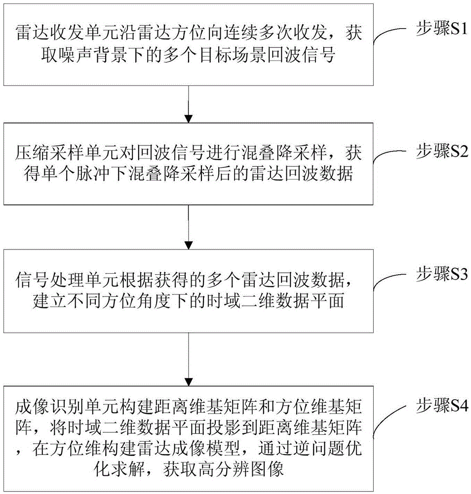
[0054] based on the following Figure 1 to Figure 6 , specifically explain the preferred embodiment of the present invention.

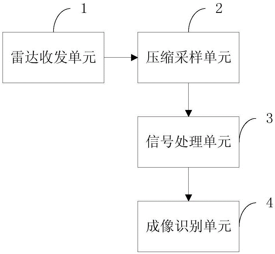
[0055] Such as figure 1 As shown, the present invention provides a high-resolution imaging device for compressive sensing radar under low signal-to-noise ratio, comprising:

[0056] The radar transceiver unit 1 is used to detect and obtain the echo signal of the target scene under the noise background;

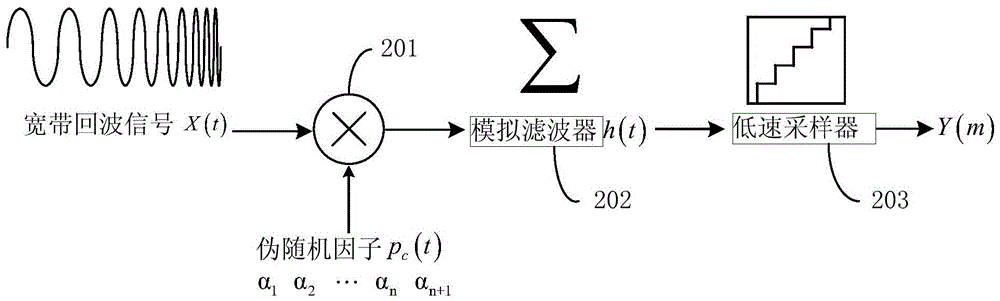
[0057] Compression sampling unit 2, the input end of which is electrically connected to the output end of radar transceiver unit 1, for compressing and down-sampling the echo signal;

[0058] The signal processing unit 3, its input end is electrically connected to the output end of the compression sampling unit 2, and is used to establish the time domain two-dimensional data plane under different azimuth angles;

[0059] The imaging recognition unit 4, whose input end is electrically connected to the output end of the signal processing unit 3, is u...


PUM


Abstract

Compression perception radar high resolution imaging equipment under a low signal to noise ratio and an imaging method thereof are disclosed. A radar transceiver unit carries out continuous multi-time transmitting and receiving along a radar azimuth and acquires a plurality of target scene echo signals under a noise background. A compression sampling unit carries out aliasing downsampling on the acquired echo signals and acquires radar echo data after aliasing downsampling under a single pulse. A signal processing unit establishes time-domain two-dimensional data planes under different orientation angles according to the plurality of radar echo data. An imaging identification unit constructs a distance dimension basis matrix and an orientation dimension basis matrix. The time-domain two-dimensional data planes are projected to the distance dimension basis matrix. A radar imaging model is constructed on the orientation dimension. Through an inverse optimization method, a high resolution image is acquired. In the invention, a small aperture radar effectively restrains a noise interference and a side lobe through a small echo data volume and simultaneously realizes high resolution imaging, and a performance index of a small aperture radar system is increased.

Description

technical field [0001] The invention relates to a compressed sensing radar high-resolution imaging device and an imaging method thereof under low signal-to-noise ratio. Background technique [0002] There are relatively mature synthetic aperture imaging methods in existing radar systems. Its imaging resolution is related to the width of the main lobe of the point spread function, and the width of the main lobe is limited by the bandwidth of the transmitted signal and the length of the azimuth synthetic aperture. Moreover, the sidelobe of conventional synthetic aperture radar imaging is relatively high. When there is noise or clutter interference in the target scene, the imaging effect will be invalid, which will affect the detection and recognition of subsequent targets. [0003] After searching domestic and foreign databases, the search results are as follows: [0004] Authorized patent CN103954963A "A Stepped Frequency SAR Imaging Method Based on CS Algorithm", the publi...

Claims


Application Information

Patent Timeline
Patent Type & Authority Applications(China)
IPC IPC(8): G01S13/90
CPCG01S13/904G01S13/9004
Inventor 张天键蔡信王志诚田原余渝生汤振华
Owner SHANGHAI RADIO EQUIP RES INST
Why Eureka
Try Eureka