Method of Determining Engineering Stable Machining Process Parameter Diagram Based on Two-Dimensional Flutter Stability Limit Diagram

A technology with processing technology and stability limit, which is used in the selection of high-speed and high-efficiency milling parameters, can solve problems such as shortening the trial production cycle, and achieve the effect of shortening the trial production cycle and improving the overall processing efficiency.

Active Publication Date: 2018-01-19
HEILONGJIANG UNIVERSITY OF SCIENCE AND TECHNOLOGY
View PDF6 Cites 0 Cited by
  • Summary
  • Abstract
  • Description
  • Claims
  • Application Information

AI Technical Summary

Problems solved by technology

[0004] The problem to be solved by the present invention is, on the basis of modal decoupling, selecting the modal vibration shape of the workpiece processing point as the main parameter, and establishing the stability limit region of the thin-walled workpiece-fixture system, fully considering the workpiece at the engineering application site Clamping, cutting resonance, modal coupling and other factors that are not easy to be considered in theory, with weighted membership degree and curve smoothness as optimization constraints, the engineering application curve and specific function expression equation of high-speed cutting thin-walled parts are given, Then quickly guide the selection of high-efficiency chatter-free milling parameters, shorten the product trial production cycle, and improve the overall processing efficiency of the high-speed milling system

Method used


Image

  • Method of Determining Engineering Stable Machining Process Parameter Diagram Based on Two-Dimensional Flutter Stability Limit Diagram
  • Method of Determining Engineering Stable Machining Process Parameter Diagram Based on Two-Dimensional Flutter Stability Limit Diagram
  • Method of Determining Engineering Stable Machining Process Parameter Diagram Based on Two-Dimensional Flutter Stability Limit Diagram

Examples


Embodiment Construction

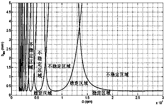
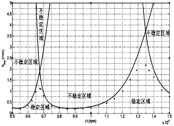
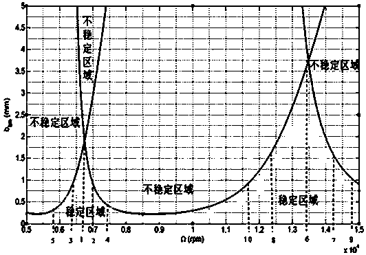
[0031] A method for determining a stable machining process parameter diagram for engineering based on a two-dimensional flutter stability limit diagram. This method is based on the two-dimensional flutter stability mechanical expression equation and limit diagram in the milling processing system, and is applied in the application range where the spindle speed of the processing equipment is 5000-15000rpm Inside, the depth of cut of the spindle speed in different ranges is corrected and the curve is smoothed according to the degree of membership value to obtain the stable machining mechanics expression equation and process parameter diagram for engineering. This method is realized by the following steps:

[0032] Step 1. Based on the process system composed of similar workpieces and fixtures that are prone to flutter and the processing system composed of tool spindles, the modal parameters of the process system, modal parameters of the processing system, and the vibration shape of...


PUM


Abstract

The invention provides a method, based on a two-dimensional flutter stability limit diagraph, for determining a stable processing technological parameter diagraph used for engineering. The method is characterized by selecting modal vibration modes of workpiece processing points on the limit diagraph as main parameters, using a weighted membership degree and a curve smoothness degree as optimization constraint conditions and providing engineered application curves and function expression equations of a high-speed cut thin-walled piece. The method comprises the steps of: in a stable processing technological parameter curve in an application interval of a main shaft rotation speed in the limit diagraph, eliminating first and second order modal frequency flutters of a technology system at a cutting depth corresponding to the main shaft rotation speed according to a multiple of the membership degree, and correcting the cutting depth based on the coupling between the first and second order modal frequency flutters of the processing system; carrying out secondary correction on the stable processing technological parameter curve after the correction; carrying out fitting and extraction of specific functions on an established engineered curve; and determining stable processing mechanical equations and the stable processing technological parameter diagraph used for engineering. The method has the advantages that the high-efficiency flutter-free milling parameters are selected, the production period of a product is shortened, and the integral processing efficiency of a high-speed milling system is improved.

Description

Technical field: [0001] The invention belongs to a method for selecting process parameters in the field of high-speed and ultra-high-speed milling, and specifically relates to the avoidance of flutter phenomena in process systems in the field of processing and the selection of high-speed and high-efficiency milling parameters. Background technique: [0002] At present, there are many effective theories and methods for obtaining the chatter stability region of the process system. However, in the actual engineering application site, many actual processing factors have not been considered, which makes the obtained chatter stability limit region not favorable. It effectively guides the selection of processing parameters at the engineering site, thereby reducing the practical application value of the stability limit curve. [0003] Take the following research content as an example: "Theory and Experimental Research on Stability of Time-delay Process System in Milling with Flexibl...

Claims


Application Information

Patent Timeline
Patent Type & Authority Patents(China)
IPC IPC(8): G05B19/408
CPCG05B19/4086G05B2219/35203
Inventor 赵灿陶广福郭延艳徐衍峰刘玉波王学惠何万涛
Owner HEILONGJIANG UNIVERSITY OF SCIENCE AND TECHNOLOGY
Why Eureka
Try Eureka