Supercharge Your Innovation With Domain-Expert AI Agents!

Inversion circuit

A technology of inverter circuit and bridge circuit, which is applied in the electronic field, can solve problems such as low utilization rate of inductance, high-frequency noise of output line, damage of switch tube, etc., and achieve the effect of improving conversion efficiency, reducing loss and reducing cost

Active Publication Date: 2016-04-06
美世乐(广东)新能源科技有限公司
View PDF7 Cites 3 Cited by
  • Summary
  • Abstract
  • Description
  • Claims
  • Application Information

AI Technical Summary

Problems solved by technology

The disadvantages of this control method are: 1. When the filter link adopts a single inductor structure, high-frequency noise will appear on the output line, which makes it difficult to control the EMI of the product
2. When the filter link adopts a dual inductor structure, the utilization rate of the inductor is very low, which reduces the conversion efficiency of the product
Due to the inconsistency of the turn-on and turn-off characteristics of the switch tube and the inconsistency of the control circuit parameters of the dead time, the two switch tubes of the same bridge arm may be turned on at the same time, resulting in damage to the switch tube

Method used


Image

  • Inversion circuit
  • Inversion circuit
  • Inversion circuit

Examples


Embodiment 1

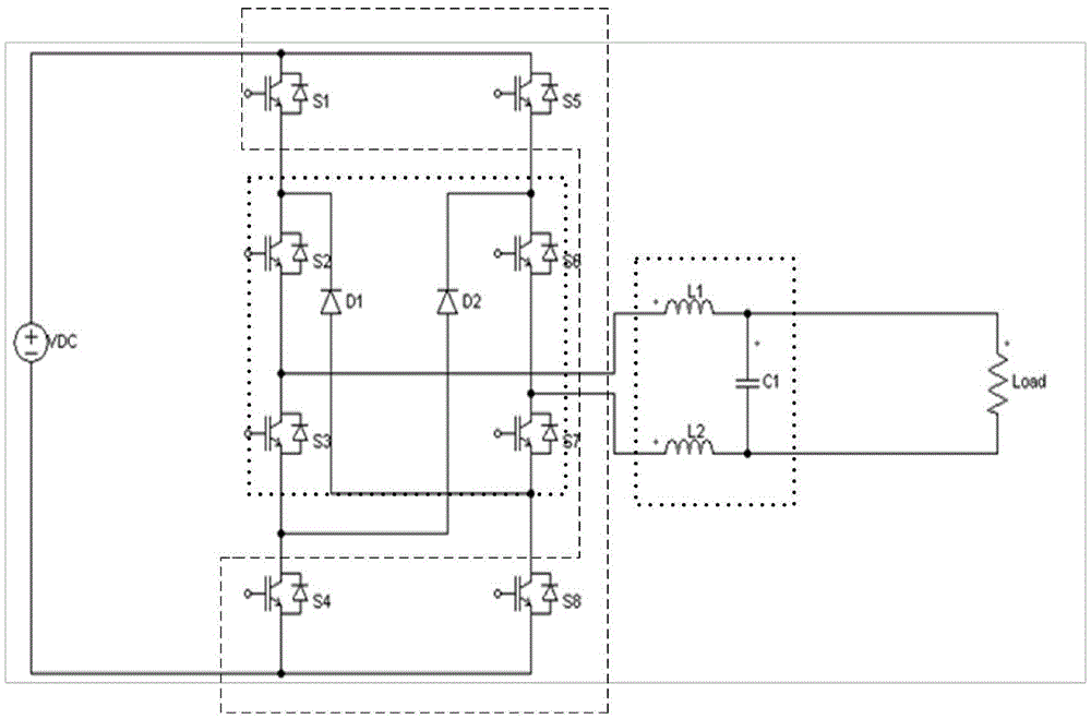
[0029] Such as Figure 7 As shown, a high-performance inverter circuit includes a DC module, an AC inverter module, a filter circuit, an AC output, a control module, and a detection module. Wherein: the control module generates a SPWM signal to control the switching tube for energy conversion. The described AC inverter module includes a bridge circuit and a freewheeling circuit that forms a freewheeling circuit together with the bridge circuit to make the LC filter circuit continue. They have four high-frequency switch tubes, four power frequency switch tubes, two freewheeling diode. The four high-frequency switching tubes form a SPWM high-frequency pulse signal, that is, the high-frequency modulation sine wave generation link composed of the first switching tube S1, the fourth switching tube S4, the fifth switching tube S5, and the eighth switching tube S8 ; produce standard sine wave output after filter circuit; said four power frequency switching tubes and two freewheelin...

Embodiment 2

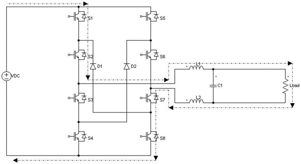
[0035] The difference from Embodiment 1 is that the inverter circuit includes a bridge circuit, an LC filter circuit, and a freewheeling circuit that forms a freewheeling circuit together with the bridge circuit to allow the LC filter circuit to continue. The bridge circuit outputs to the LC filter circuit. circuit, the two adjacent bridge arms of the upper bridge arm of the bridge circuit are respectively connected in series with switch tubes. The bridge circuit includes a first switch tube, a second switch tube, a fifth switch tube, a sixth switch tube, a seventh switch tube and a third switch tube, and the first switch tube and the second switch tube are connected in series to form the first switch tube. In the first bridge arm, the fifth switch tube and the sixth switch tube are connected in series to form the second bridge arm, the seventh switch tube forms the third bridge arm, and the third switch tube forms the fourth bridge arm. The freewheeling circuit includes first...

Embodiment 3

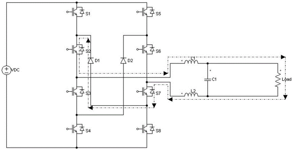
[0037] Two adjacent bridge arms of the lower bridge arm are respectively connected in series with switch tubes. The bridge circuit includes a second switch tube, a sixth switch tube, a seventh switch tube, an eighth switch tube, a third switch tube and a fourth switch tube, the second switch tube constitutes the first bridge arm, and the sixth switch tube The tube forms the second bridge arm, the eighth switch tube and the seventh switch tube are connected in series to form the third bridge arm, and the fourth switch tube and the third switch tube are connected in series to form the fourth bridge arm. The freewheeling circuit includes first and second freewheeling diodes, and the first freewheeling diode and the second freewheeling diode are respectively connected to the junction between the input terminal of the upper bridge arm and the switch tube connected in series with the lower bridge arm. point.


PUM


Abstract

The invention relates to an inversion circuit. The inversion circuit includes a bridge type circuit, an LC filtering circuit and a freewheeling circuit, wherein the freewheeling circuit and the bridge type circuit together form a freewheeling loop so as to make the LC filtering circuit realize freewheeling; the output of the bridge type circuit is connected with the LC filtering circuit; and two adjacent bridge arms of the upper bridge arms or / and lower bridge arms of the bridge type circuit are respectively connected in series with a switching tube. According to the technical schemes of the invention, the switching tubes of the two inversion bridge arms are in off states; at least two switching tubes in a circuit loop are in off states, and therefore, two-end voltage of a first switching tube, a second switching tube, a third switching tube, a fourth switching tube, a fifth switching tube, a sixth switching tube, a seventh switching tube and an eighth switching tube is at least 1 / 2 of input voltage; in the whole working process of the inversion circuit of the invention, two switching tubes on the same bridge arm are constantly in off states, and therefore, low-voltage switching tubes can be adopted, and therefore, loss can be reduced, the performance of products can be improved, and cost can be reduced, and conversion efficiency can be improved.

Description

technical field [0001] The invention belongs to the field of electronics, and in particular relates to a power inverter circuit and its control method. Background technique [0002] With the rapid development of power electronics technology, research on traditional circuit structures has gradually deepened, and new circuit structures have been proposed continuously. The inverter link in the power supply adopts a traditional inverter circuit, that is, a full-bridge inverter circuit. This circuit mainly has two control methods: the first is unipolar SPWM modulation, and the second is bipolar SPWM modulation. [0003] For the first control method of unipolar SPWM modulation, the two switching tubes of the opposite bridge arm form a group, in which the switching tube of the lower bridge arm is driven by SPWM mode, and a standard sine wave is generated after filtering; the switching tube of the upper bridge arm Driven by power frequency signal, it mainly realizes the commutation...

Claims


Application Information

Patent Timeline
IPC IPC(8): H02M7/48H02M7/5387H02M1/44
CPCH02M1/44H02M7/48H02M7/5387H02M1/0054Y02B70/10
Inventor 丁平张武
Owner 美世乐(广东)新能源科技有限公司
Features
  • R&D
  • Intellectual Property
  • Life Sciences
  • Materials
  • Tech Scout
  • Unparalleled Data Quality
  • Higher Quality Content
  • 60% Fewer Hallucinations
Learn More