A Micro Thin Film Resistance Heater

A thin film resistor and heater technology, applied in ohmic resistance heating, electric heating devices, electrical components, etc., can solve the problems of limited material selection, small size, difficult block packaging, etc., to reduce thermal time constant and improve thermal controllability. the effect of improving the heating efficiency

Active Publication Date: 2018-09-11
HUBEI JIEXUN PHOTOELECTRIC
View PDF4 Cites 0 Cited by
  • Summary
  • Abstract
  • Description
  • Claims
  • Application Information

AI Technical Summary

Problems solved by technology

[0003] The advantage of the resistance wire heater is that it can achieve a larger heating area, higher heat transfer efficiency (heat convection velocity), and can be made into a large-area heater such as an electric kettle, a hot air fan, etc.; its disadvantage is that it is difficult to achieve a small and Not suitable for bulk packaging in small devices, and operational control is not easy
[0004] Traditional thick-film resistance heaters, such as standard SMD thick-film resistors, have the advantage of small size and are suitable for block mounting; their disadvantages are that the heating surface is three-dimensional, that is, it does not heat on one side. For two-dimensional surface heating elements In terms of heating, it will inevitably lead to a reduction in heat transfer efficiency and power; at the same time, due to the existence of welding ends (metal) at both ends, the material selection of the heating element is limited, that is, it is not suitable for good contact and bonding with non-metallic heating materials.
[0005] The thermoelectric controller (TEC) has the advantages of relatively small size and relatively flexible structure, but the cost is high
[0006] The advantage of the traditional thin-film resistance heater is that the size can be made very small, but because most of its sheet resistance is currently in a certain range, such as 10~1000Ω / □, its application in micro heaters is limited to a certain extent.
[0007] When the thin-film resistance heater is used in micro-devices, sometimes there is a forbidden area in the middle of the heating resistance substrate. The general heating element of the heater has the requirement of uniform heating. Generally, the ring heating layout structure is adopted, such as figure 1 As shown, the circular ring is the resistance area, and the two extended areas are the gold layer soldering areas. The main defect of this structure is that it is difficult to make the resistance value below 200Ω under the condition of limited size, and the widest reach 0.15mm , then 10Ω / □*3 / 0.15=200Ω, so the maximum resistance value is 200Ω

Method used


Image

  • A Micro Thin Film Resistance Heater
  • A Micro Thin Film Resistance Heater
  • A Micro Thin Film Resistance Heater

Examples


Embodiment 1

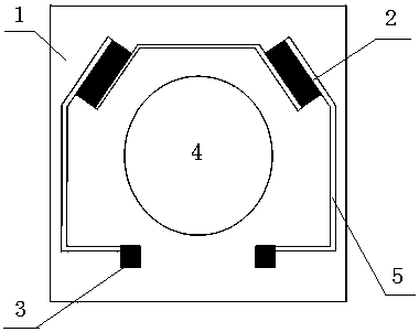
[0037] Embodiment 1: as figure 2 As shown, the number of area units of the resistive sheet 2 is 2, and the two resistive sheets 2 are arranged on one side of the substrate 1, symmetrically along the forbidden area, and the pad 3 is arranged on the other side of the substrate 1, and the two resistive sheets 2 Connect to pad 3 in series through a wire.

Embodiment 2

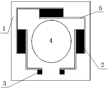
[0038] Embodiment 2: as image 3 As shown, the number of area units of the resistive sheet 2 is 3, and each resistive sheet 2 is arranged in the middle of the three sides of the substrate 1, and the pad 3 is arranged in the middle of the fourth side of the substrate 1, and the three resistive sheets 2 pass through The wire is connected to pad 3 in series.

Embodiment 3

[0039] Embodiment 3: as Figure 4 As shown, the number of area units of the resistive sheet 2 is 4, each resistive sheet 2 is arranged at the four corners of the substrate 1, each resistive sheet 2 is symmetrical, and the pads 3 and 4 are arranged in the middle of any side of the substrate 1 A resistance sheet 2 is connected in series with the pad 3 through a wire.

[0040] Figure 5 , Figure 6 It is a technical scheme in which resistor sheets 2 are connected in parallel.


PUM


Abstract

The invention relates to a micro thin-film resistance heater. A keep-out region 4 is arranged in the middle of a substrate 1; the keep-out region 4 is a heated element, an optical channel or a structural part; the substrate 1 is square or round; the periphery of the keep-out region 4 is plated with resistance chips 2; the resistance chips 2 are arranged according to regional units; the heated element is heated uniformly through layout distribution of the units; the number of the regional units of the resistance chips 2 is greater than or equal to 2; and the regional units of the resistance chips 2 are connected in series or in parallel through lead wires. The micro thin-film resistance heater is tiny in size, low in power consumption, high in heat efficiency and easy to attach to a micro-device, breaks through process limitation of conventional thin-film resistance, meets the demand on the keep-out region in a compact structure, and is suitable for products such as photoelectron devices, micro-electron devices, passive optical devices and the like.

Description

technical field [0001] The invention relates to a miniature resistance heater, in particular to a miniature thin-film resistance heater. Background technique [0002] At present, micro-small resistance heaters are commonly used in resistance wire type, thick film resistance chip type, TEC semiconductor type, and thin film resistance type. [0003] The advantage of the resistance wire heater is that it can achieve a larger heating area, higher heat transfer efficiency (heat convection velocity), and can be made into a large-area heater such as an electric kettle, a hot air fan, etc.; its disadvantage is that it is difficult to achieve a small and Not suitable for bulk packaging in small devices, and operational control is not easy. [0004] Traditional thick-film resistance heaters, such as standard SMD thick-film resistors, have the advantage of small size and are suitable for block mounting; their disadvantages are that the heating surface is three-dimensional, that is, it...

Claims


Application Information

Patent Timeline
Patent Type & Authority Patents(China)
IPC IPC(8): H05B3/00
CPCH05B3/0014
Inventor 黎凯庞正达杨昕卢卫东
Owner HUBEI JIEXUN PHOTOELECTRIC
Why Eureka
Try Eureka