One-step granulation system for ultrafine powder

A fluidization chamber and fan blade technology, applied in the field of one-step granulation, can solve the problems of low granulation efficiency, large material loss, and easy to generate electrostatic adsorption, etc., to achieve uniform fluidization, improve granulation efficiency, and improve balance Yield effect

Active Publication Date: 2018-06-12
ZHONGSHAN ZHONGZHI PHARMA GRP
View PDF4 Cites 0 Cited by
  • Summary
  • Abstract
  • Description
  • Claims
  • Application Information

AI Technical Summary

Problems solved by technology

[0006] With the rise of modern ultrafine pulverization technology, the overall particle size of raw and auxiliary materials after ultrafine pulverization is mostly less than 45µm, of which the particle size is 0.1µm-10µm accounting for more than 20%, and 10µm-30µm accounts for 60%. As mentioned above, for this kind of raw material powder after ultrafine treatment, because its particle size is too small, it is easy to produce electrostatic adsorption, so the air distribution plate with conventional planar hollow structure is used for one-step granulation of ultrafine powder In the process of powder fluidization, there will still be powder sticking and powder accumulation on one side of the cavity, and the air flow distribution plate in the prior art cannot achieve uniform fluidization of the material.
In addition, if a conventional dust collection device is used to granulate ultrafine powder, the powder is easily entrained by the airflow, and the solid powder carried by the exhaust gas will be discharged through the aperture of the dust-proof bag, resulting in large material loss. The granulation efficiency is low, which affects the performance and practical application of the final product of ultrafine powder. Therefore, it is necessary to improve the existing one-step granulation system so that it can achieve efficient granulation of ultrafine powder

Method used


Image

  • One-step granulation system for ultrafine powder
  • One-step granulation system for ultrafine powder
  • One-step granulation system for ultrafine powder

Examples


Embodiment 1

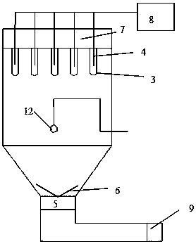
[0034] A one-step granulation system, the main structure diagram is as follows figure 1 .

[0035] The main body of the one-step granulation system includes, from top to bottom, an induced air cavity 7, a spray fluidization chamber 13, an atomization nozzle 12, a pneumatic stirring blade 6, a screen, and an air flow dividing plate 5. The atomization nozzle 12 is located at In the center of the cavity of the spray fluidization chamber 13, the atomization nozzle 12 is connected with the liquid feed pipe placed on the side of the cavity of the spray fluidization chamber 13, and the top of the spray fluidization chamber 13 is provided with the air induction cavity 7 The through hole 10 is connected with a titanium rod filter 3, and the center of the through hole 10 is provided with a nozzle 4, which has a vertical tubular structure and extends to the cavity of the spray fluidization chamber 13, when When the titanium rod filter 3 is connected to the through hole 10, the nozzle 4 is l...

Embodiment 2

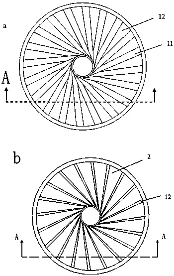
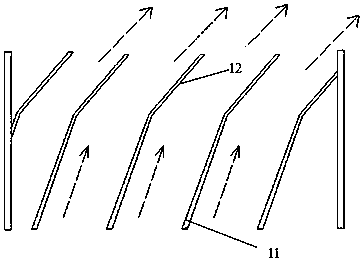
[0042] The bottom view and the top view of the air flow divider plate 5 in Example 1 are respectively figure 2 a and 2b, the A-A line cross-sectional view is as image 3 .

[0043] The air flow distribution plate 5 includes two hollow cylinders inside and outside. The two ends of the first fan blade 1 are mounted on the two hollow cylinders, which are in a fan-like structure. The first fan blade 1 includes a first blade surface 11 and a first blade surface. Two blade surfaces 12, one end of the first blade surface 11 is at the air inlet position, the other end is connected with the second blade surface 12, one end of the second blade surface 12 is at the air outlet position, and the other end is connected with the first blade surface 11 The included angle between the first blade surface 11 and the second blade surface 12 of the first fan blade 1 is an obtuse angle; the first fan blade 1 is spaced between 0.5 cm and 1.5 cm, and is evenly distributed in two Hollow cylinder. The i...

Embodiment 3

[0046] This embodiment is improved on the basis of Embodiment 2. The bottom view and the top view of the air distribution plate 5 of this embodiment are the same as those of Embodiment 2, and the cross-sectional view along line A-A is as Figure 4 .

[0047] In this embodiment, in the second blade surface 12 of the first fan blade 1 described in the second embodiment, a second fan blade 2 is installed at the end close to the air outlet; the second fan blade 2 and the first fan blade 1 have the same Length, there is an angle between the second fan blade 2 and the first fan blade 1, and a distance from the outer surface of the first fan blade 1 arranged adjacently.

[0048] The working principle of the air distribution plate: the purified hot air blown from below the air distribution plate enters the air distribution plate 5 through the first leaf surface 11 along the way, and the hot air passes through the first leaf surface 11 and the second leaf surface 12 The angle between the tw...


PUM

PropertyMeasurementUnit
particle diameteraaaaaaaaaa
pore sizeaaaaaaaaaa
pore sizeaaaaaaaaaa

Abstract

The invention relates to the technical field of one-step granulation, and discloses a one-step granulation system for ultrafine powder, including a spray fluidization chamber, and an air distribution plate is arranged below the screen at the bottom of the spray fluidization chamber, and the spray The upper part of the fluidization chamber is provided with an air induction chamber, and the top of the spray fluidization chamber is provided with a through hole communicating with the air induction chamber. The through hole is connected with a titanium rod filter, and the center of the through hole is provided with a nozzle. One end is connected to the compressed air blowback device; the air distribution channel formed by the air flow distribution plate and the air flow distribution plate surface of the fluidized bed present a channel angle of 30-60°, thereby changing the direction of the air intake, increasing the wind speed, and simultaneously entering the air The whole is rotating, which is conducive to improving the uniform state of fluidization; the pore size of the titanium rod filter is 0.1-10 µm, which can effectively block ultra-fine dust and reduce leakage of materials; The dust accumulated on the titanium rod filter is dusted off to improve the granulation efficiency of the powder.

Description

Technical field [0001] The present invention relates to the technical field of one-step granulation, and more specifically, to a one-step granulation system of ultrafine powder. Background technique [0002] Fluidized bed granulation, also known as boiling granulation, refers to the use of airflow to suspend the powder material in a boiling state, and then spray the atomized binder to make the powder granulate, and finally obtain the dry granule. In this process, the material is mixed , Granulation and drying are completed at the same time, so it is also called one-step granulation. [0003] The one-step granulation system is generally composed of dust collection system, spray fluidization chamber, raw material container, control system and other parts. The working process is that the purified air enters the raw material container through the bottom after being heated. The hot air heats the material and makes it fluidized. At this time, the binder is sprayed in in the form of a mi...

Claims


Application Information

Patent Timeline
Patent Type & Authority Patents(China)
IPC IPC(8): B01J2/10
Inventor 成金乐刘海李武毅朱国胜罗石坚唐琳徐吉银
Owner ZHONGSHAN ZHONGZHI PHARMA GRP
Why Eureka
Try Eureka