
Thin plate welding method

A technology for thin plate welding and welding direction, which is applied in welding equipment, arc welding equipment, manufacturing tools, etc., to achieve the effect of improving the appearance quality

Inactive Publication Date: 2016-04-13
XI AN RAILWAY TRANSPORTATION EQUIP
View PDF7 Cites 2 Cited by
  • Summary
  • Abstract
  • Description
  • Claims
  • Application Information

AI Technical Summary

Problems solved by technology

[0007] In order to solve the problems of the existing welding technology mentioned in the background technology, the present invention provides a thin plate welding method, which effectively solves the problem of deformation and improves the quality of welding

Method used


Image

  • Thin plate welding method
  • Thin plate welding method

Examples


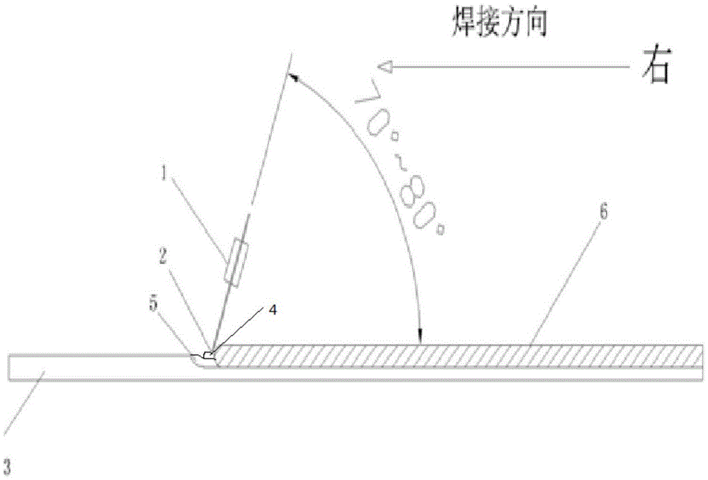
Embodiment Construction

[0021] The technical solution of the present invention is described in detail below by means of the accompanying drawings;

[0022] The sheet welding method includes the following steps:

[0023] 1) Place the thin plate to be welded fixedly, turn on the switch of the welding torch, the welding wire in the welding torch will protrude and generate an arc with the welding part of the weldment;

[0024] 2) Operate the welding torch to make the arc contact with the thin plate to be welded and form a molten pool;

[0025] 3) After the molten pool is formed, start welding;

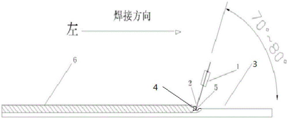
[0026] During welding, the welding torch is welded in a straight line at a constant speed along the welding direction; the arc generated by the welding torch is at an angle of 70° to 80° to the thin plate to be welded in the welding direction.

[0027] Usually the right welding method used in metal arc welding, such as figure 1 As shown; weld from right to left. During welding, due to the direct heating of th...


PUM


Abstract

The invention relates to a thin plate welding method. The thin plate welding method includes the following steps that firstly, a thin plate to be welded is fixedly arranged, a welding gun switch is turned on, and a welding wire in the welding gun stretches out to generate an electric arc with a part, to be welded, of a weldment; then, the welding gun is operated so that the electric arc can be in contact with the thin plate to be welded to form a molten pool; finally, after the molten pool is formed, welding is started; and during welding, the welding gun conducts linear welding at a constant speed in the welding direction, and an angle of 70-80 degrees is formed by the electric arc generated by the welding gun and the thin plate to be welded in the welding direction. The thin plate welding method mainly solves the problem that a current thin plate is prone to being burnt through, and meanwhile the problem of welding deformation is reduced, and the welding appearance quality is obviously improved. The productivity is also improved obviously and is improved to existing 800-1200 mm / min from original 400-600 mm / min.

Description

technical field [0001] The invention belongs to the field of railway transportation workpiece welding, and relates to a welding method, in particular to a thin plate welding method. Background technique [0002] The roof and car body of the railway P70 general-purpose box car adopt lap joints of 1.5mm thick thin plates, and are welded by gas shielded welding. poor. By improving the welding operation mode and adopting a reasonable operation method, the welding quality can be guaranteed and the production efficiency can be improved. The existing welding method mainly has the following disadvantages: [0003] 1. Large welding deformation; [0004] 2. It is inconvenient to observe the edge of the plate during welding, it is easy to weld deviation, and the welding wire points directly to the molten pool, and the arc has a scouring effect on the molten pool. If the operation is improper, the weld reinforcement will be too large, which will affect the weld shape; [0005] 3. Th...

Claims


Application Information

Patent Timeline
Patent Type & Authority Applications(China)
IPC IPC(8): B23K9/173B23K9/025
CPCB23K9/173B23K9/025
Inventor 李永军王建红贾汝唐
Owner XI AN RAILWAY TRANSPORTATION EQUIP
Learn More