
Voltage-reduction constant-current type eddy current retarder control system based on pulsing bias amplification

A technology of eddy current retarder and control system, which is applied in electric braking system, electric vehicle, transportation and packaging, etc. It can solve the problems of complex wiring harness, lack of working voltage, and inability to stabilize the control of eddy current retarder. Achieve the effects of reducing wiring harness, improving braking performance and improving reliability

Inactive Publication Date: 2016-04-13
CHENGDU KERUIXIN TECH CO LTD
View PDF5 Cites 0 Cited by
  • Summary
  • Abstract
  • Description
  • Claims
  • Application Information

AI Technical Summary

Problems solved by technology

[0004] The purpose of the present invention is to overcome the traditional eddy current retarder control system wiring harness complex, and does not have a stable working voltage, resulting in its inability to stably control the eddy current retarder, to provide a pulse bias based Amplified step-down constant current eddy current retarder control system

Method used


Image

  • Voltage-reduction constant-current type eddy current retarder control system based on pulsing bias amplification
  • Voltage-reduction constant-current type eddy current retarder control system based on pulsing bias amplification
  • Voltage-reduction constant-current type eddy current retarder control system based on pulsing bias amplification

Examples


Embodiment

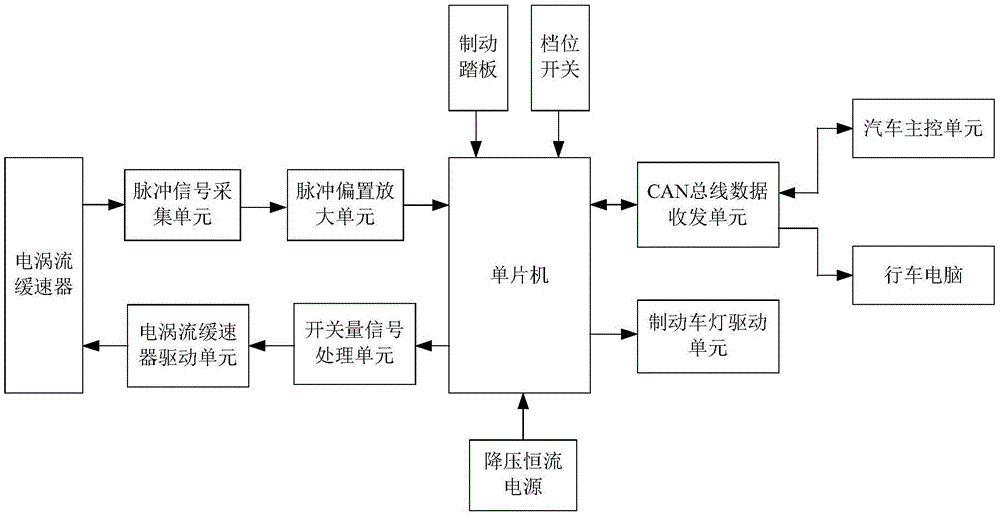
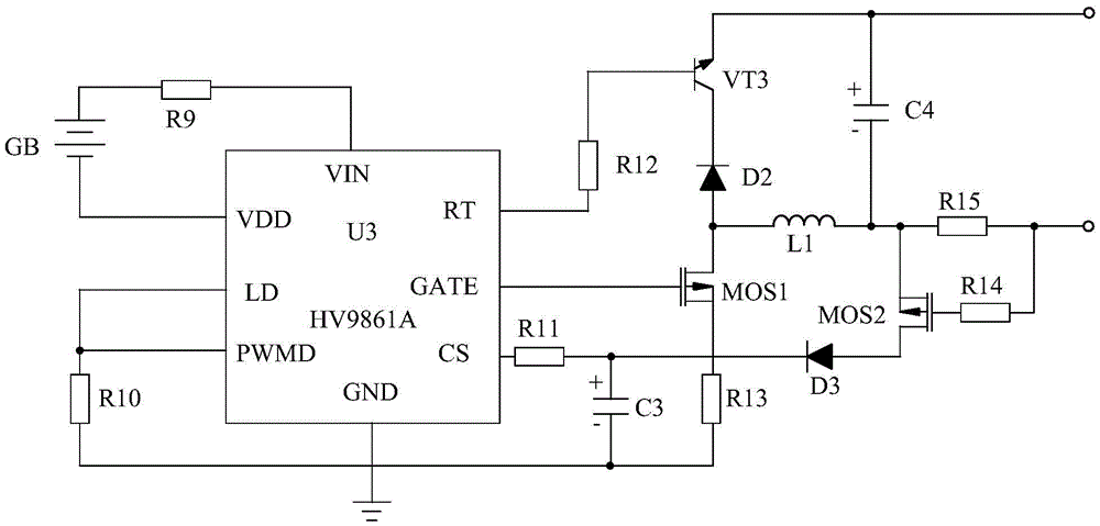
[0021] Such as figure 1 As shown, the step-down constant current eddy current retarder control system based on pulse bias amplification of the present invention is driven by an eddy current retarder, a pulse bias amplification unit, a pulse signal acquisition unit, and an eddy current retarder Unit, switch signal processing unit, single chip microcomputer, brake pedal, gear switch, step-down constant current power supply, CAN bus data transceiver unit, brake light drive unit, car main control unit and trip computer 13 parts.

[0022] Among them, the single-chip microcomputer is used as the control center of the present invention, and it is respectively connected with the step-down constant current power supply, the brake pedal, the gear switch, the pulse bias amplification unit, the switch value signal processing unit, the CAN bus data transceiver unit and the brake light drive. unit is connected. The vehicle main control unit and the driving computer are respectively connect...


PUM


Abstract

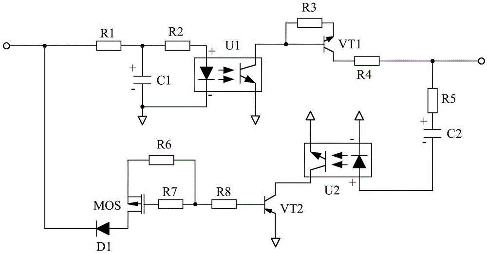
The invention discloses a voltage-reduction constant-current type eddy current retarder control system based on pulsing bias amplification. The voltage-reduction constant-current type eddy current retarder control system comprises an eddy current retarder, and is characterized by further comprising a single-chip microcomputer, a voltage-reduction constant-current electric source, a brake pedal, a gear switch, a switching value signal processing unit, a CAN bus data transmitting and receiving unit, a brake lamp driving unit, a pulse bias amplifying unit, an automobile main control unit, a driving computer, an eddy current retarder driving unit, and a pulse signal acquisition unit, wherein the voltage-reduction constant-current electric source, the brake pedal, the gear switch, the switching value signal processing unit, the CAN bus data transmitting and receiving unit, the brake lamp driving unit and the pulse bias amplifying unit are connected with the single-chip microcomputer; the automobile main control unit and the driving computer are connected with the CAN bus data transmitting and receiving unit; the eddy current retarder driving unit is connected with the switching value signal processing unit; the pulse signal acquisition unit is connected with the pulsing bias amplifying unit; the eddy current retarder is connected with the pulse signal acquisition unit and the eddy current retarder driving unit at the same time. According to the voltage-reduction constant-current type eddy current retarder control system disclosed by the invention, the pulse bias amplifying unit can amplify load signals of the eddy current retarder without enabling the load signals to be undistorted, so that the eddy current retarder control system disclosed by the invention can accurately reflect the real-time operational state of the eddy current retarder.

Description

technical field [0001] The invention relates to an eddy current retarder control system, in particular to a step-down constant current eddy current retarder control system based on pulse bias amplification. Background technique [0002] Eddy current retarder is an auxiliary braking device for automobiles, commonly known as electric brake, which is mainly used in large passenger cars, urban buses and heavy trucks. The device is installed between the car drive axle and the gearbox, and realizes non-contact braking through the principle of electromagnetic induction. [0003] With the popularity of eddy current retarders and the increasing number of electrical systems on passenger cars, more and more information exchanges between eddy current retarders and other electrical systems such as ABS systems and engine control systems, while traditional electrical signals The control method leads to more and more complicated wiring harness of the eddy current retarder control system, w...

Claims


Application Information

Patent Timeline
Patent Type & Authority Applications(China)
IPC IPC(8): B60L7/28
CPCB60L7/28
Inventor 陈仁学
Owner CHENGDU KERUIXIN TECH CO LTD
Learn More