
Steel fiber tensioning and clamping fixture and steel fiber tensile strength testing system

A technology for clamping fixtures and steel fibers, which is applied in the direction of applying stable tension/pressure to test the strength of materials, measuring devices, strength characteristics, etc. The difference of fiber tensile properties and other problems can avoid adverse effects, uniform force and easy installation.

Inactive Publication Date: 2016-04-13
ZHENGZHOU UNIV
View PDF7 Cites 13 Cited by
  • Summary
  • Abstract
  • Description
  • Claims
  • Application Information

AI Technical Summary

Problems solved by technology

However, for a long time, due to the lack of corresponding test equipment, especially the lack of tension fixtures that can effectively clamp steel fibers, it is difficult to directly obtain the tensile properties of steel fibers.
In practice, the parameters of the tensile properties of steel fibers are often obtained by making standard tensile specimens from the parent material according to the tensile test methods of conventional materials, but because different types of steel fibers are produced in different ways process, the process will have a certain impact on the tensile properties of the finished steel fiber, resulting in a difference in the tensile properties of the steel fiber and its parent material, which will have an adverse effect on the reasonable selection of steel fibers, especially for cutting high-strength steel wires. steel fiber

Method used


Image

  • Steel fiber tensioning and clamping fixture and steel fiber tensile strength testing system
  • Steel fiber tensioning and clamping fixture and steel fiber tensile strength testing system
  • Steel fiber tensioning and clamping fixture and steel fiber tensile strength testing system

Examples


Embodiment Construction

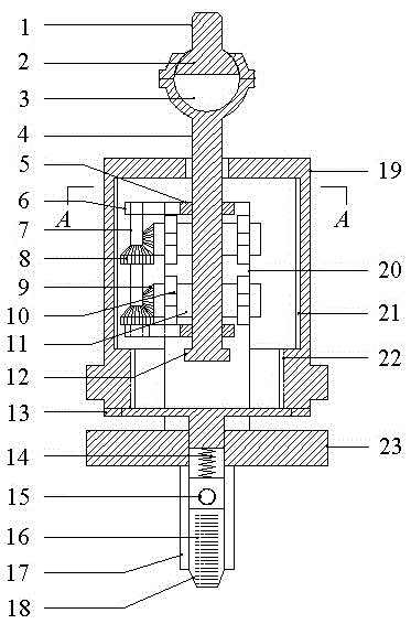
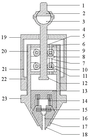
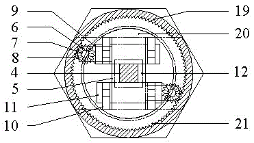
[0032] Such as figure 1 , figure 2 and image 3 As shown, the steel fiber tension clamping fixture includes a main support 23, a load transmission mechanism and a steel fiber specimen clamping and locking mechanism.

[0033] The center of the main bracket 23 is provided with a square guide hole passing through the upper end surface and the lower end surface, and two limbs 20 are provided on both sides of the square guide hole connected with the main bracket 23;

[0034] The load transfer mechanism includes a square column toothed tie rod 4, a limit plate 5 to ensure the linear movement of the toothed tie rod 4, an anti-off baffle 12, a gear transmission assembly and a tightening cap 19; the limit plate 5 is connected horizontally Set on the top of the two limb arms 20 and the middle part of the inner side wall, the center of the limit plate 5 is provided with a square guide hole, the guide hole is provided with a toothed pull rod 4, and the lower end of the toothed pull rod...


PUM


Abstract

The invention discloses a steel fiber tensioning and clamping fixture and a steel fiber tensile strength testing system. The steel fiber tensioning and clamping fixture comprises a main bracket, a load transmission mechanism and a steel fiber test piece clamping and locking mechanism, and clamping pieces can effectively clamp and tension a steel fiber test piece in the tensioning process; the steel fiber tensile strength testing system comprises two sets of steel fiber tensioning and clamping fixtures and a data acquisition device, the data acquisition device comprises a load sensor, an extensometer and a controller, the two sets of steel fiber tensioning and clamping fixtures are used for clamping the steel fiber test piece, the extensometer is arranged on the steel fiber test piece, output ends of the load sensor and the extensometer are connected with two input ends of the controller, and an output end of the controller is connected with a computer. According to the steel fiber tensioning and clamping fixture and the steel fiber tensile strength testing system, the tensile strength and the deformation parameters of steel fibers as well as the stress-strain complete curve in the steel fiber breakage process can be accurately tested.

Description

technical field [0001] The invention relates to the technical field of engineering testing and testing, in particular to a steel fiber tension clamping fixture and a steel fiber tensile performance testing system. Background technique [0002] Steel fiber reinforced concrete is a new type of multi-phase formed by distributing short and thin steel fibers uniformly and chaotically in the ordinary concrete matrix, acting as a "bridge" between the concrete matrix and the aggregate, and making the concrete material tend to be isotropic. composite material. These randomly distributed steel fibers can effectively prevent the expansion of micro-cracks and the formation of macro-cracks in concrete, significantly improve the tensile, bending, impact and fatigue properties of concrete, and have good ductility and toughness, while steel fibers The performance of these excellent properties of concrete depends largely on the tensile strength of steel fibers relative to the concrete matri...

Claims


Application Information

Patent Timeline
IPC IPC(8): G01N3/16G01N3/04
CPCG01N3/04G01N3/16G01N2203/0017G01N2203/028G01N2203/0447G01N2203/0458
Inventor 汤寄予高丹盈赵军卢纪富王宝庭杨淑慧胡嵘晖曾垂林
Owner ZHENGZHOU UNIV
Learn More