Mass transfer apparatus

A circulating and high-efficiency technology, applied in the field of mass transfer devices and electric equipment, can solve the problems of increasing the volume and power of heaters, limiting the length of a reaction, and increasing energy consumption, so as to achieve high space utilization, prolong reaction and Operating time and the effect of reducing power consumption

Active Publication Date: 2016-04-13
JOINT CO AKME ENG
View PDF3 Cites 1 Cited by
  • Summary
  • Abstract
  • Description
  • Claims
  • Application Information

AI Technical Summary

Problems solved by technology

[0003] The defects in the design of the above-mentioned device are: firstly, the storage capacity of the solid particle oxidant limits the length of a reaction, if the reaction time is prolonged by increasing the capacity and loading of the reaction chamber, the volume and power of the heater must be increased , which will inevitably lead to an increase in power consumption; on the other hand, there are also problems in the maintenance process of this equipment. When the oxidant needs to be reloaded, the liquid metal oxidant in the reaction chamber and the cylindrical shell needs to be extracted at the same time

Method used


Image

  • Mass transfer apparatus

Examples


Embodiment Construction

[0020] The present invention will be further described below in conjunction with the accompanying drawings.

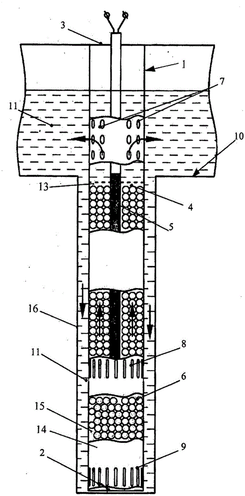
[0021] Such as figure 1 As shown (the following are all conventional numbers in this field), wherein: 1—shell, 2—bottom, 3—top, 4—restrictive porous grid, 5—electric heater, 6—solid particle oxidant, 7—exit, 8—inlet, 9—liquid outlet, 10—heat carrier storage tank, 11—liquid metal heat carrier, 13—flow reaction chamber, 14—bottom of oxidant storage chamber (cup-shaped body), 15—particle oxidant storage chamber, 16 - Outer cover.

[0022] The device according to the embodiment of the present invention comprises a space surrounded by a housing 1 and composed of a bottom 2 and an annular top 3 . In this space, a flow reaction chamber 13 is arranged below the liquid level of the liquid metal heat carrier 11, and a restrictive porous grid 4 is arranged on the top of the flow reaction chamber 13, the purpose of which is to restrict the solid particle oxidant 6 under the acti...


PUM


Abstract

The invention relates to energy mechanical engineering and can be used in power installations involving a liquid-metal heat carrier. A mass transfer apparatus including a housing and, provided therein, a flow reaction chamber filled with a solid-phase granulated oxidation agent, and an electric heater positioned in the reaction chamber. The housing of the apparatus is equipped with a repository for reserves of the solid-state granulated oxidation agent, said repository being located below the reaction chamber and being made in the form of a cup having a bottom, said cup being connected to the reaction chamber. The technical result consists in extending the operational duration of the mass transfer apparatus.

Description

technical field [0001] The mass transfer device of the invention relates to the field of energy mechanical engineering and can be applied to power equipment containing liquid lead heat carrier. Background technique [0002] The closest prior art of the present invention is the Russian patent (patent number: 2246561, C23F11 / 00, 20.02.2005) disclosing a mass transfer device. The device comprises: a casing; a flow reaction chamber located in the casing and filled with a solid particle oxidant; an electric heater arranged in the flow reaction chamber; a porous grid located on the top of the flow reaction chamber as an oxygen-enriched liquid metal heat carrier outlet; The perforated grid used as the inlet of liquid metal heat carrier. The return channel has a ring structure. The shell of the device is arranged in a cylindrical shell, and a heat carrier channel is arranged on the shell, and the channel is connected with an annular channel formed between the shell of the device a...

Claims


Application Information

Patent Timeline
Patent Type & Authority Applications(China)
IPC IPC(8): B01J8/00B01F1/00
CPCG21C15/00G21C1/02G21C17/0225G21C19/28Y02E30/30G21C19/02B01J2208/065B01J8/008B01J8/0015B01J8/0285B01J2208/00415B01J2208/00752B01J2208/00761
Inventor 马丁诺夫·裴特·尼基弗若维奇艾斯克哈杜林·拉多米尔·莎米利维奇司马科夫·安德烈·艾利克斯维奇里歌奇·艾利克萨德·尤瑞维奇
Owner JOINT CO AKME ENG
Why Eureka
Try Eureka