Catalytic cracking light product desulfurization method, and method and device for catalytic cracking production of low-sulfur light oil product

A technology of catalytic cracking and light products, which is applied in the field of desulfurization and separation of catalytic cracking rich gas and naphtha, and hydrocarbon oil desulfurization. Effects of saturation and saving hydrogen consumption

Active Publication Date: 2021-05-04
CHINA PETROLEUM & CHEM CORP +1
View PDF4 Cites 2 Cited by
  • Summary
  • Abstract
  • Description
  • Claims
  • Application Information

AI Technical Summary

Problems solved by technology

[0005] The technical problem to be solved by the present invention is to solve the problems of low yield and high octane number loss of stable gasoline produced by catalytic cracking units, and provide a method for desulfurization and separation of catalytic cracking light products to obtain desulfurized dry gas, liquefied Gasoline and FCC Stabilized Gasoline

Method used


Image

  • Catalytic cracking light product desulfurization method, and method and device for catalytic cracking production of low-sulfur light oil product
  • Catalytic cracking light product desulfurization method, and method and device for catalytic cracking production of low-sulfur light oil product
  • Catalytic cracking light product desulfurization method, and method and device for catalytic cracking production of low-sulfur light oil product

Examples


Embodiment 1

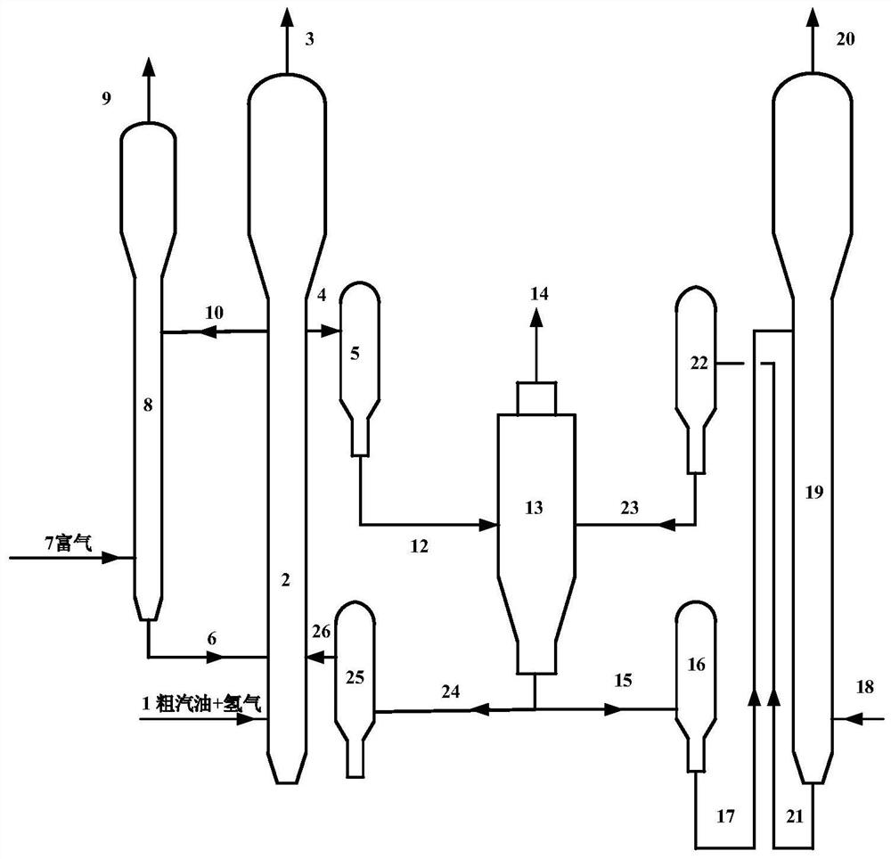
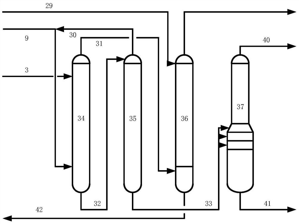
[0072] Using rich gas and crude gasoline as raw materials, it first enters the adsorption desulfurization reaction unit, and then enters the absorption stabilization unit for separation. figure 1 The process of adsorption desulfurization unit and the process of absorption stabilization unit are as attached figure 2 As shown, the first desulfurization reactor is a small fixed fluidized bed reactor, and the second desulfurization reactor is a countercurrent reactor. The desulfurization adsorbent used is FCAS. The desulfurization adsorbent from the reducer enters the first desulfurization reactor from the bottom, and naphtha and hydrogen enter the first desulfurization reactor from the bottom to contact with the desulfurization adsorbent for adsorption and desulfurization. After the reaction is completed, The reaction oil gas is separated from the desulfurization adsorbent to obtain a mixture of desulfurized naphtha and hydrogen; part of the desulfurization adsorbent on the top ...

Embodiment 2

[0074] Use as attached figure 1 And attached figure 2 The flow process of the desulfurization and separation method shown in the adsorption desulfurization unit and the absorption stabilization unit uses rich gas and naphtha as raw materials, adopts the same reaction process and desulfurization adsorbent as in Example 1, the difference is that the first desulfurization The reactor is at a reaction temperature of 430°C, a reaction pressure of 1.4MPa, and a weight hourly space velocity of 8h -1 , under the reaction conditions of hydrogen oil volume ratio of 100. Preheat the rich gas to 430°C and enter the second desulfurization reactor. At a reaction temperature of 445°C, a reaction pressure of 0.5MPa, and a weight hourly space velocity of 12h -1 The first desulfurization reactor obtains desulfurized naphtha and hydrogen, and the second desulfurization reactor obtains desulfurized rich gas. Wherein, 60% of the position from bottom to top of the first desulfurization reactor ...


PUM


Abstract

The present invention provides a catalytic cracking light product desulfurization method and device. The method comprises the following steps: (1) introducing crude gasoline from a fractionating tower of a catalytic cracking device into a first desulfurization reactor, carrying out contact desulfurization on the crude gasoline and a desulfurization adsorbent in the presence of hydrogen, and enabling the crude gasoline to flow upwards; and enabling one part of the sulfur-loaded adsorbent separated by gas-solid separation to enter the upper part of the second desulfurization reactor, and roasting, regenerating and recycling the other part of the sulfur-loaded adsorbent and oxygen-containing gas in an adsorbent regenerator, wherein the separated reaction oil gas is desulfurized crude gasoline; (2) carrying out countercurrent contact adsorption desulfurization reaction on the desulfurization adsorbent in the second desulfurization reactor and rich gas, and returning the desulfurization adsorbent to the first desulfurization reactor after the reaction; and (3) respectively feeding the desulfurized rich gas and the desulfurized crude gasoline to an absorption and stabilization unit for further separation to obtain desulfurized dry gas, liquefied gas and stable gasoline. The method provided by the invention is suitable for treating rich gas and crude gasoline obtained by a catalytic cracking fractionating tower, and the obtained refined gasoline is high in yield and low in octane number loss.

Description

technical field [0001] The invention belongs to the field of petrochemical industry, and relates to a method for desulfurizing hydrocarbon oil, more specifically, a method for desulfurizing and separating catalytic cracking rich gas and naphtha. Background technique [0002] The catalytic cracking unit in the refinery is the main source of light olefins, liquefied petroleum gas and gasoline. In the existing catalytic cracking process, the reaction products of the catalytic cracking unit can be fractionated to obtain rich gas, naphtha, light diesel oil, and heavy diesel oil and oil slurry and other components. The rich gas passes through the absorption desorption tower and the reabsorption tower to obtain dry gas products, and the dry gas can be used as refinery fuel gas after desulfurization. Liquefied gas and catalytic cracking stable gasoline can be obtained after the crude gasoline is separated by the absorption and stabilization tower. The catalytic cracking gasoline ca...

Claims


Application Information

Patent Timeline
Patent Type & Authority Applications(China)
IPC IPC(8): C10G67/02C10G69/04C10G70/04
CPCC10G67/02C10G69/04C10G70/046C10G2400/02C10G2400/26C10G2300/1044C10G2300/104C10G2300/202
Inventor 毛安国王文寿刘宪龙徐莉刘玉良
Owner CHINA PETROLEUM & CHEM CORP
Why Eureka
Try Eureka