
Micro-liquid-drop transportation method based on y-shaped cut lithium niobate wafer

A technology for cutting lithium niobate and micro-droplets, which is applied to the analysis of materials and instruments, can solve the problems of local light response, complex chip structure, and poor controllability of transport operations, so as to achieve simple chip structure, reduce adverse effects, The effect of synchronous transport

Inactive Publication Date: 2016-04-20
HEBEI UNIV OF TECH
View PDF3 Cites 19 Cited by
  • Summary
  • Abstract
  • Description
  • Claims
  • Application Information

AI Technical Summary

Problems solved by technology

[0007] The currently reported microdroplet transport methods have disadvantages such as complex chip structure, poor controllability of transport action, and localized photoresponse.

Method used


Image

  • Micro-liquid-drop transportation method based on y-shaped cut lithium niobate wafer
  • Micro-liquid-drop transportation method based on y-shaped cut lithium niobate wafer
  • Micro-liquid-drop transportation method based on y-shaped cut lithium niobate wafer

Examples


example 1

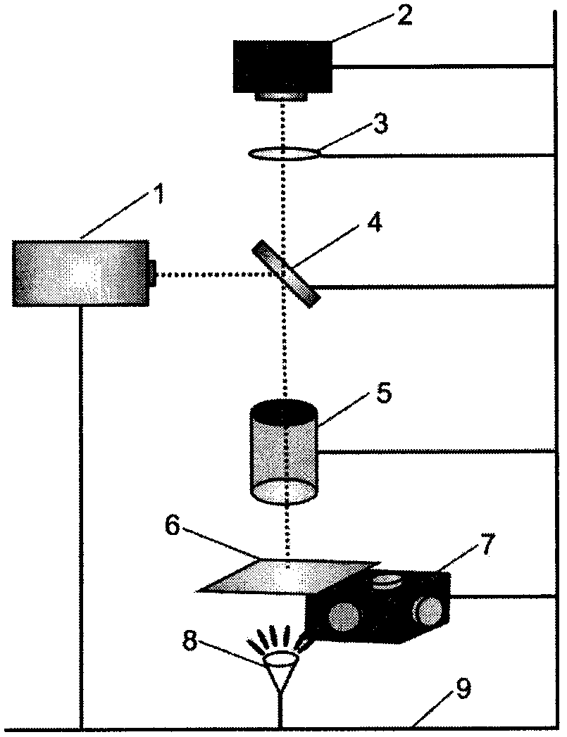
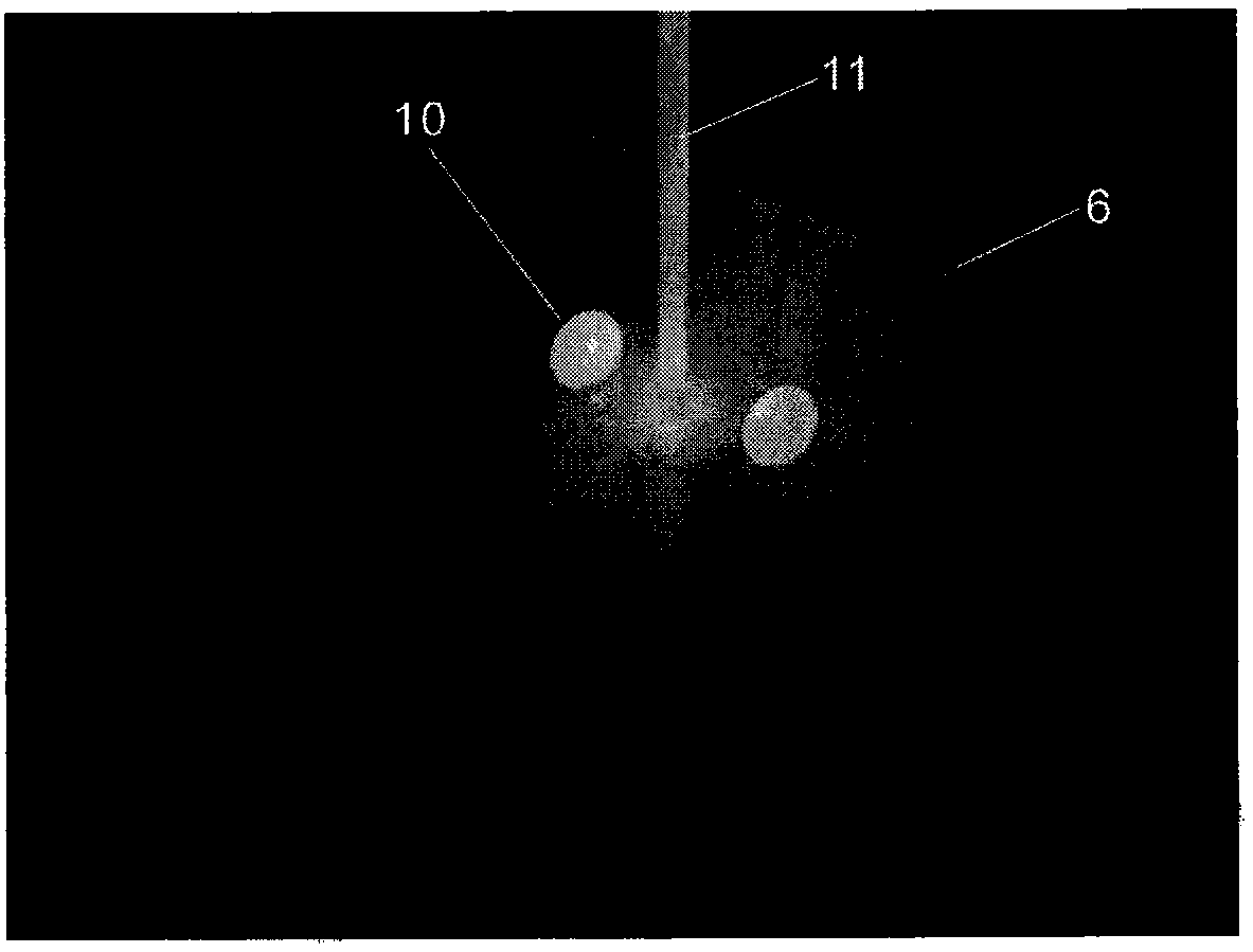
[0029] Using a 488nm laser, a halogen lamp is used as the background light source, and the magnification of the focusing objective lens is 25 times, a micro-droplet with a volume of 55.1pL is introduced onto a y-cut lithium niobate wafer, and then the laser is turned on to adjust the spatial position of the micro-droplet so that It is located near the focused laser spot, and the focus light power is adjusted to 38mW. The y-cut lithium niobate wafer is driven by a three-axis micro-movement translation stage, so that the laser spot scans along a certain path on its surface, and the micro-droplets will move together with the laser spot to realize the transportation of micro-droplets. The speed is 215um / s, and a certain distance is kept between the micro-droplet and the light spot during the transport process.

example 2

[0031] Using a 488nm laser, white LED as the background light source, and a magnification of 25 times the focusing objective lens, a micro-droplet with a volume of 60.8pL is introduced onto a y-cut lithium niobate wafer, and then the laser is turned on to adjust the spatial position of the micro-droplet so that It is located near the focused laser spot, and the focused light power is adjusted to 46mW. The y-cut lithium niobate wafer is driven by a three-axis micro-movement translation stage, so that the laser spot scans along a certain path on its surface, and the micro-droplets will move together with the laser spot to realize the transportation of micro-droplets. The speed is 263um / s, and the distance between the micro-droplet and the light spot is maintained during the transportation process.

example 3

[0033] Use a 405nm laser, white LED as the background light source, and 25 times the magnification of the focusing objective lens. Two micro-droplets with volumes of 15.1pL and 75.4pL are introduced onto the y-cut lithium niobate wafer, and then the laser is turned on to adjust the micro-droplets. The spatial position makes the focused laser spot hit the middle of the two droplets, and adjusts the focused light power to 3.65mW. The y-cut lithium niobate wafer is driven by a three-axis micro-movement translation stage, so that the laser spot scans along a certain path on its surface, and the micro-droplet will move with the laser spot to realize the transportation of two micro-droplets. The transport speed is 17um / s, and a certain distance is kept between the micro-droplet and the light spot during the transport process.


PUM


Abstract

The invention discloses a micro-liquid-drop transportation method. The method takes a y-shaped cut lithium niobate wafer as a chip substrate and takes a dielectrophoresis force generated by irradiating the lithium niobate wafer through laser focusing as a driving force of micro-liquid-drops; and the micro-liquid-drops are driven by scanning motion of laser focusing light spots on the lithium niobate wafer to be transported according to a random two-dimensional path. According to the method disclosed by the invention, the structure of a needed chip is simple, and the transportation motion of the micro-liquid-drops is accurately and flexibly adjusted and controlled through controlling a light spot scanning speed and laser power. Furthermore, the method also has the characteristics of non-local light response, double-liquid-drop synchronous transportation and the like. The technology can be used for transporting micro-medicaments and fluid samples in biological, chemical and medical analysis processes, and has very important meanings on the development of fields including biological medicine, drug diagnosis, environment monitoring and molecular biology and the like.

Description

technical field [0001] The invention relates to a micro-droplet control technology, in particular to a micro-droplet transport method with simple chip structure, flexible control of transport action, and non-local light response characteristics. Background technique [0002] Micro-droplet manipulation technology is usually used for the separation and transportation of micro-drugs and fluid samples in the process of biological, chemical, and medical analysis, and can be applied to microfluidic chips that integrate basic operating units such as culture, reaction, separation, and detection. Design and development are of great significance to the development of biomedicine, drug diagnosis, food hygiene, environmental monitoring, and molecular biology. [0003] In 2003, W.H.Grover et al. (Monolithic membrane valves and diaphragm pumps for practical large-scale integration into glass microfluidic devices, Sens. Actuators B, 89, 315-323 (2003)), used a micro air pump device compose...

Claims


Application Information

Patent Timeline
IPC IPC(8): G01N35/10
CPCG01N35/1095
Inventor 陈立品阎文博樊博麟李少北陈洪建
Owner HEBEI UNIV OF TECH
Learn More