
Fault diagnosis circuit for electronic circuit

A fault diagnosis and electronic circuit technology, applied in the direction of electronic circuit testing, measuring electricity, measuring electrical variables, etc., can solve the problems of inconvenient fault detection of electronic circuit equipment, extremely difficult diagnosis and judgment work, poor portability and use performance, etc. , to improve the accuracy and detection efficiency, a wide range of fault detection, and improve the scope of application.

Inactive Publication Date: 2016-04-20
STATE GRID CORP OF CHINA +1
View PDF7 Cites 2 Cited by
  • Summary
  • Abstract
  • Description
  • Claims
  • Application Information

AI Technical Summary

Problems solved by technology

[0002] At present, with the improvement of automation and integration of electrical equipment, the use of various electronic circuits is very large. When the circuit equipment fails, it is extremely difficult to diagnose and judge the fault point. In view of this situation, a variety of professional electronic circuit equipment fault diagnosis circuits have been developed to deal with the detection and diagnosis of electronic circuit equipment faults. But in use, it is found that the currently used electronic circuit equipment fault diagnosis circuit can only detect and diagnose faults of single or similar types or faults of electronic circuits, but in the process of diagnosis, the operation is relatively complicated , the detection efficiency is low and the accuracy of the detection results is relatively poor, so it cannot effectively meet the requirements of the current electronic circuit types and fault types that need to be detected, thus causing great inconvenience to the fault detection of electronic circuit equipment. There are also some detection devices with various functions, but these devices are often bulky, costly to use, and relatively poor in portability and performance, so they still cannot meet the needs of actual use. In view of this situation, it is urgent to develop a structure Simple, easy-to-use and low-cost invented electronic circuit detection circuit structure to meet the needs of practical use

Method used


Image

  • Fault diagnosis circuit for electronic circuit
  • Fault diagnosis circuit for electronic circuit
  • Fault diagnosis circuit for electronic circuit

Examples


Embodiment Construction

[0015] In order to make the technical means, creative features, goals and effects achieved by the present invention easy to understand, the present invention will be further described below in conjunction with specific embodiments.

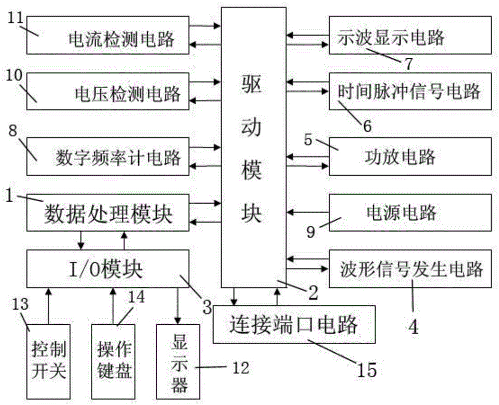
[0016] like figure 1 Described a kind of electronic circuit fault diagnosis circuit, comprises data processing module 1, drive module 2, I / O module 3, waveform signal generation circuit 4, power amplifier circuit 5, time pulse signal circuit 6, oscilloscope display circuit 7, digital Frequency meter circuit 8, power supply circuit 9, voltage detection circuit 10, current detection circuit 11, display 12, control switch 13, operation keyboard 14 and connection port circuit 15, wherein drive module 2 is connected with data processing module 1 and waveform signal generation circuit respectively 4. Power amplifier circuit 5, time pulse signal circuit 6, oscilloscope display circuit 7, digital frequency counter circuit 8, power supply circuit 9, voltag...


PUM


Abstract

The invention relates to a fault diagnosis circuit for an electronic circuit. The fault diagnosis circuit comprises a data processing module, a driving module, an I / O module, a waveform signal generation circuit, a power amplification circuit, a time pulse signal circuit, an oscillographic display circuit, a digital frequency meter circuit, a power circuit, a voltage detection circuit, a current detection circuit, a displayer, a control switch, an operation keyboard and a connecting port circuit, wherein the driving module is electrically connected with the data processing module, the waveform signal generation circuit, the power amplification circuit, the time pulse signal circuit, the oscillographic display circuit, the digital frequency meter circuit, the power circuit, the voltage detection circuit, the current detection circuit and the connecting port circuit, and the data processing module is electrically connected with the I / O module. By means of the fault diagnosis circuit, on one hand, the accuracy and efficiency of detecting the running state and the fault of the electronic circuit are greatly improved; on the other hand, the structure of detection equipment for the electronic circuit is greatly simplified, and the carrying and using convenience of the detection equipment is improved.

Description

technical field [0001] The invention relates to an electronic circuit fault diagnosis circuit, which belongs to the technical field of electronic circuit fault detection equipment. Background technique [0002] At present, with the improvement of automation and integration of electrical equipment, the use of various electronic circuits is very large. When the circuit equipment fails, it is extremely difficult to diagnose and judge the fault point. In view of this situation, a variety of professional electronic circuit equipment fault diagnosis circuits have been developed to deal with the detection and diagnosis of electronic circuit equipment faults. But in use, it is found that the currently used electronic circuit equipment fault diagnosis circuit can only detect and diagnose faults of single or similar types or faults of electronic circuits, but in the process of diagnosis, the operation is relatively complicated , the detection efficiency is low and the accuracy of the...

Claims


Application Information

Patent Timeline
Patent Type & Authority Applications(China)
IPC IPC(8): G01R31/28
CPCG01R31/2836
Inventor 王伟范春磊闫伟周威峰刘奇志周学军张赟刘晗张鹍朱勤
Owner STATE GRID CORP OF CHINA
Learn More